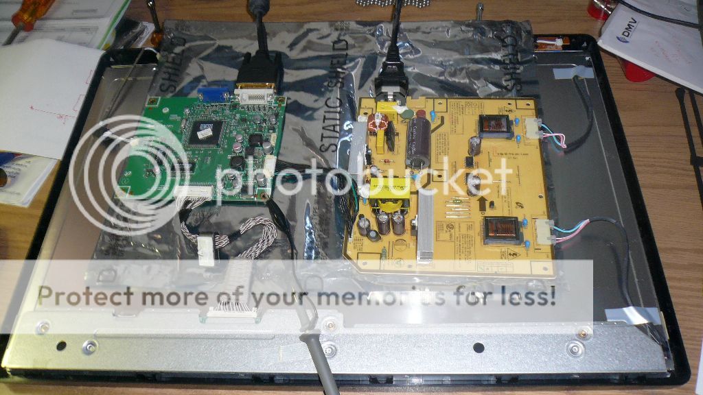
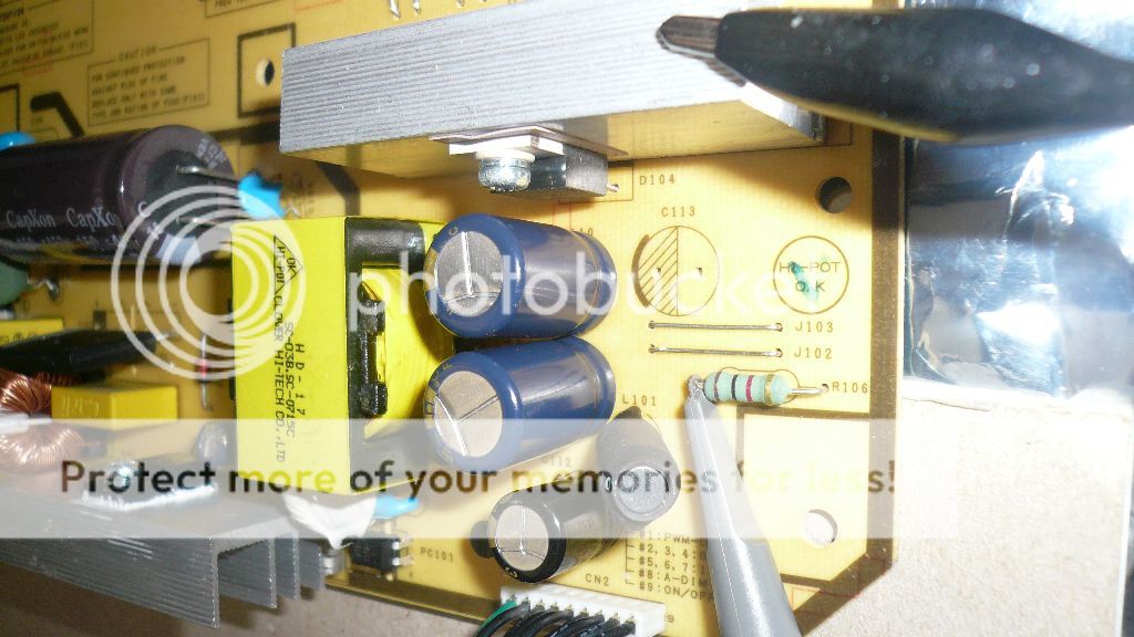
Anybody have a schematic for the power supply board found in Samsung's SyncMaster 226BW and similar model LCDs? The model number for these boards is IP-45130A. (BN44-00127x is Samsung's number for this board, with x = F or C and maybe other letters.)
Thank you...
Thank you...


Comment