Announcement

Collapse
No announcement yet.

Power supply build quality pictorial. part 2

Collapse
This is a sticky topic.
X
X
 
  • Filter
  • Time
  • Show
Clear All
new posts

    HiPro HP-P3017F3 rev:03

    Still have reservations against the previously posted HEC Orion HP585d PSU I showed? Okay, let's compare it with something a little more standard, then. By standard, I mean an OEM unit of the same class. In this case, I picked the HiPro HP-P3017F3. It's a super-popular PSU, used frequently by many PC brands like Dell, HP, Acer, and etc. It's also a PSU I seem to get quite frequently on my bench – not because it's crap, but only because it has crap caps. So, let's have a look. First, the case, as usual:
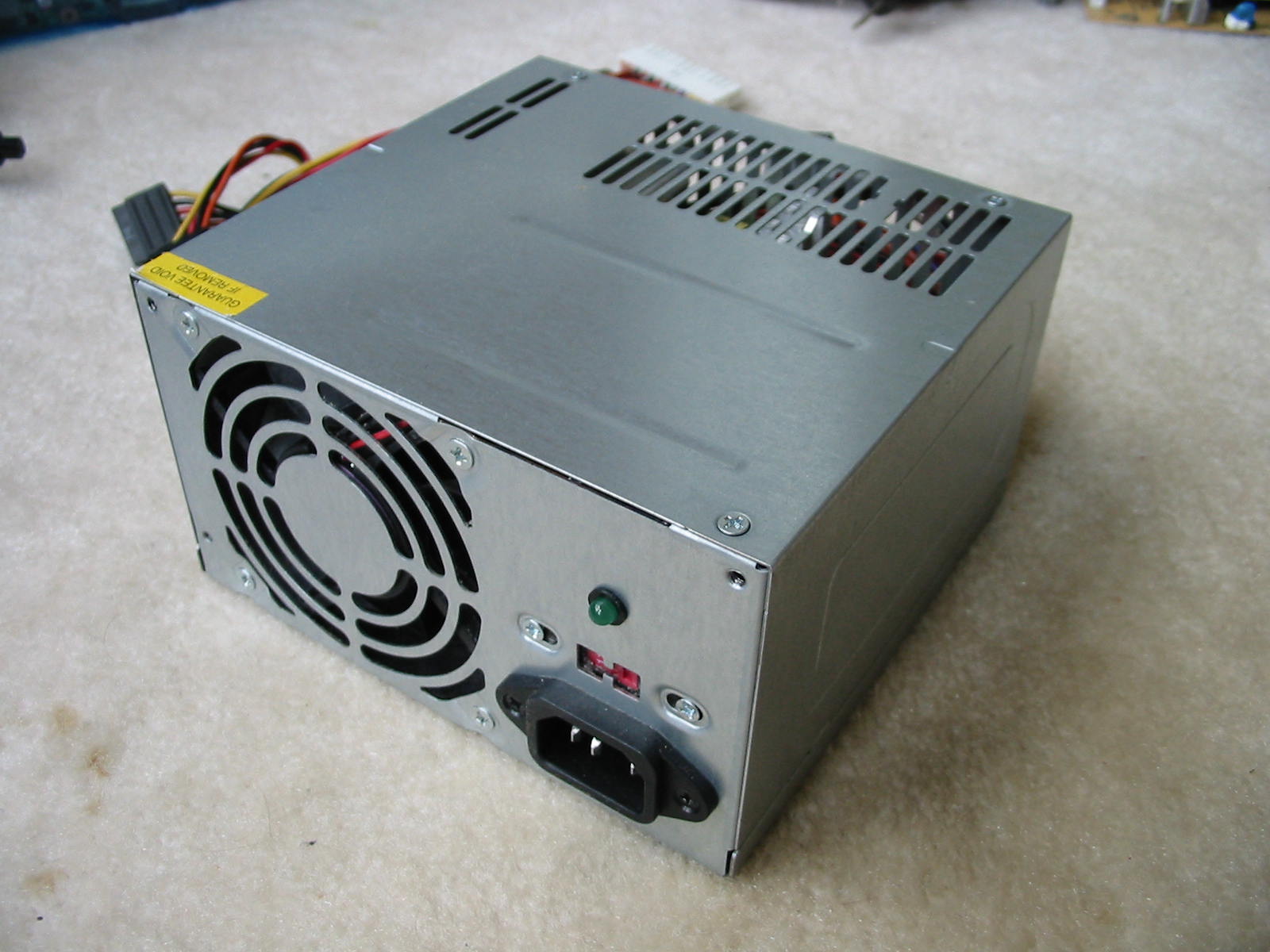
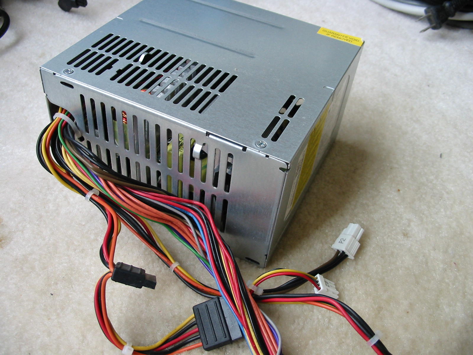
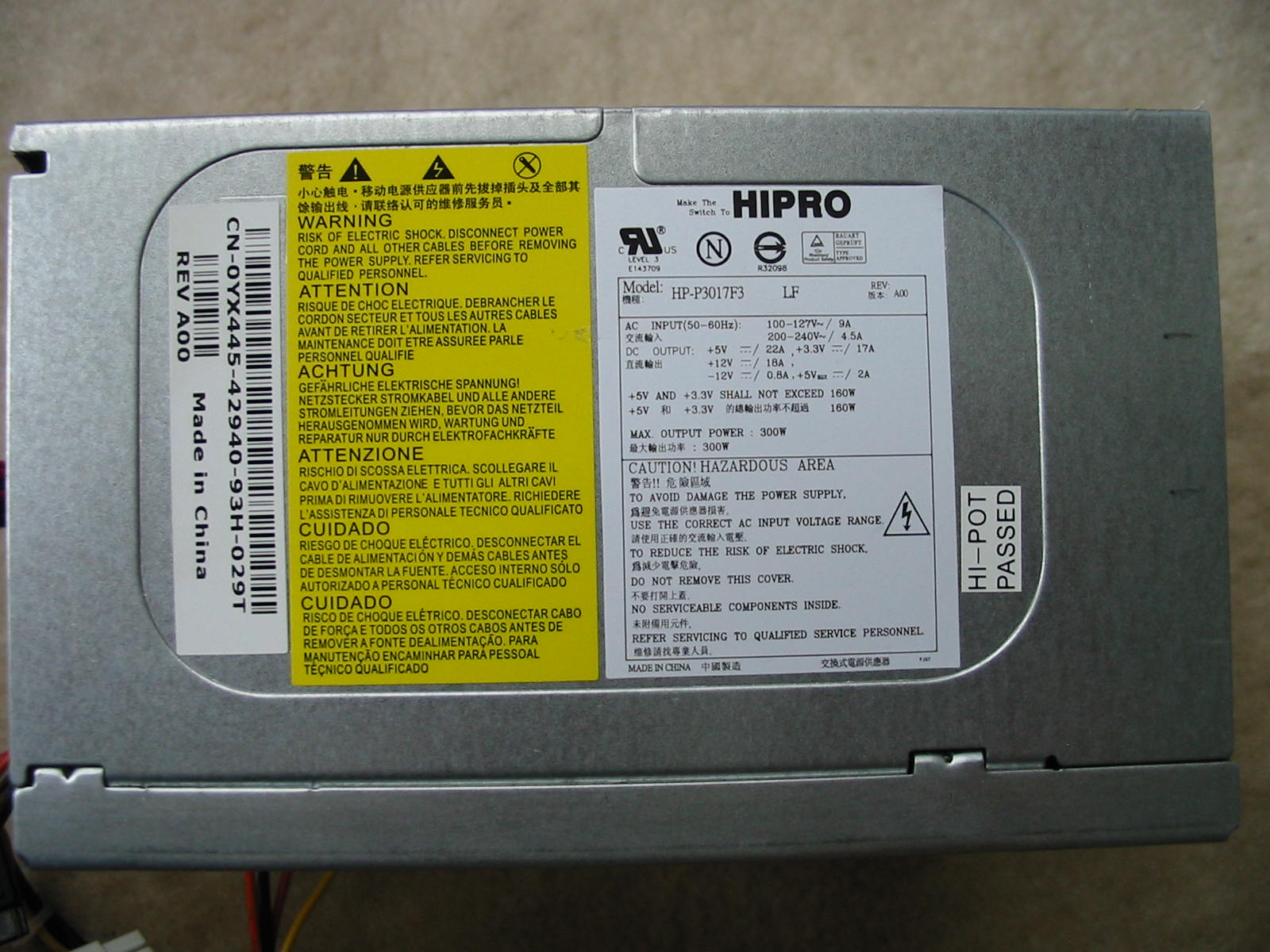
    *Yawn*
    It's just a 305W PSU in a plain steel case with short colorful wires and not a whole lot of connectors (only 4x SATA and a 4-pin 12V CPU connector, besides the 24-pin ATX). Booooring!

    But as plain as it may seem, it does get the job done. Here is what you get inside this 300-Watter:
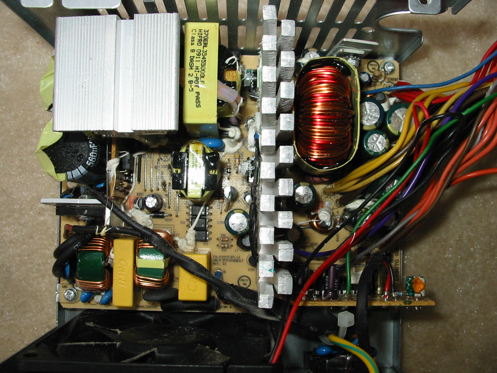
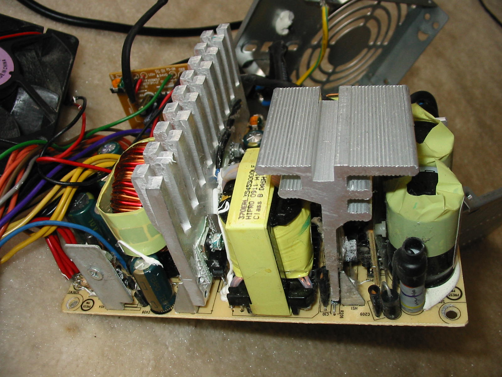

    Not bad at all, right? This PSU has very thick heatsinks, good input EMI/RFI filtering (unlike the HEC Orion HP585d… though the ThermalTake TR2-430W is about the same as the HiPro above), excellent output filtering with lots of space for the output caps, nice size output torroid and… really good size everything for just a 305 Watt unit. Design-wise, it's a single-transistor forward, just like the HEC Orion posted previously. The only slight difference is in the protections: this HiPro uses a Weltrend WT7525 IC on the secondary, which also does OCP for the 12V rail (vs. the HEC Orion, which appears to have some kind of external circuit for that.) And I consider the 5VSB of this HiPro better than the HEC Orion, as it uses a TNY266PN PWMFET IC instead of a dated 2-transistor self-oscillating circuit with a risky critical cap.

    Speaking of the secondary side above, here it is closer:
    https://www.badcaps.net/forum/attach...1&d=1578792576
    https://www.badcaps.net/forum/attach...1&d=1578792576
    Yes, now you really see why I get these for repair so often: bad caps.
    The particular unit above has Teapo SC caps. However, this is not the only brand/series found in these PSUs. Some also come with Ltec LZP and occasionally a Teapo SY thrown in there, along with a United Chemicon KZE for one of the caps on the 12V rail. Of course, the Teapo SC and Ltec LZP are the ones that fail most consistently – particularly on the 5VSB and 3.3V rails (though recently I got two units with failed Teapo SC caps on the 5V rail – and these are big 4700 uF caps in 12.5 mm diameter, which I haven't seen fail very often.) So in short, expect to do a full recap if you get one of these PSUs and you want 100% reliability. Aside from that and removing the large load resistor on the 12V rail that tends to cook the caps, there is nothing else that needs to be done on these units. With good caps, they are extremely reliable. Here is the one above when I recapped it (back ~2013) with caps I had on hand:
    https://www.badcaps.net/forum/attach...1&d=1578792576
    In case you are wondering what those black caps are: Nichicon HZ 6.3V, 2200 uF pulled from Xbox 360 motherboards. Despite being the lowest-ESR electrolytic caps (which is usually *not* recommended for PSU repair), this HiPro worked just fine with them. No squealing or hiccups (it was an experiment on my side, but it worked.) Sharp eyes may also notice I replaced that hot load resistor on the 12V rail (R422) next to the output torroid. Original value was 75 Ohms and 3-Watt power rating (because it dissipates around 2 Watts @ 12V! ) I used a single 1000-Ohm resistor, as that's all I had at the time. Could probably have even gone without, though. Getting rid of the original resistor there and using a higher value resistance is highly recommended.

    Caps aside, the secondary is done in a similar way to the HEC Orion: Separate 3.3V, 5V, and 12V rails that all go to the same torroid, with the 3.3V rail being linearly-regulated through a MOSFET afterwards.

    And before I finish off this post, here is a picture of the PCB / solder side:
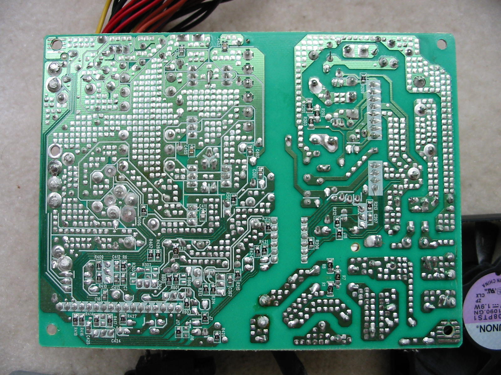
    Excellent soldering, yes?

    Oh, and these HiPro PSUs like to use a foam pad (for electrical insulation) on the bottom of the PSU case below the primary side.
    https://www.badcaps.net/forum/attach...1&d=1578792576
    Not sure if that's a good idea or not, as I'm pretty sure the foam will rot eventually and leave a mess. But at least the primary solder-side should stay dust-free (and I think this is what HiPro intended with this) for a while.

    Anyways, off to a detailed part list summary…

    ICs:
    UC384_b (PWM controller), Weltrend WT7525 (secondary-side supervisor), TNY266PN (5VSB PWM+FET combo), and 7912 linear regulator (-12V rail)

    Wiring:
    * 600V, 18 AWG input wiring
    * 300V, 18 AWG output wiring, except ATX connector (mostly 20 AWG)
    * Output connectors: 24pin ATX, 4-pin 12V CPU, 4x SATA

    Primary Side:
    * Input Filtering: two 0.47 uF X2-class caps, five Y2-class caps, two CM chokes
    * Input protection: 13R inrush current limiter, three MOVS for surge prot., T10AH fuse
    * BU1006 bridge rectifier
    * 2x 200V, 560 or 680 uF (capacity and brand varies with models), 85°C caps

    Secondary Side:
    * 5VSB
    *** 1x Teapo SC or Ltec LZP, 10V, 2200 uF, 10x20 mm before PI coil
    *** 1x Teapo SC or Ltec LZP, 10V, 470 uF, 8x13 mm after PI coil (note: space for this cap has 5 mm lead spacing and can accommodate a 10 mm diameter cap, if needed)
    *** 3A (?) schottky diode for rectification
    *** PI coil: 6-turn, 20-AWG, 4 mm core

    * 3.3V Rail
    *** 1x Teapo SC or Ltec LZP, Teapo SY, 10V, 2200 uF, 10x20 mm before linear regulator
    *** 1x Teapo SC or Ltec LZP, 10V, 2200 uF, 10x20 mm after linear regulator
    *** 1x Teapo SC, 10V, 1000 uF, 10x15 mm after linear regulator
    *** one STPS3045 (?) rectifier and CEP703AL MOSFET for linear regulation
    *** PI coil: 5.5-turn, 16-AWG, 4 mm core
    *** Load resistor: 560-Ohm, 1/8 –Watt

    * 5V Rail
    *** 1x Teapo SC, 10V, 4700 uF, 12.5x25 mm with PI coil in between
    *** two STPS3045 rectifiers in parallel
    *** PI coil: 5.5-turn, 16-AWG, 4 mm core
    *** Load resistor: 75-Ohm, ½ -Watt

    * 12V Rail
    *** 2x Teapo SC or Ltec LZP, 16V, 2200 uF, 10x30 mm
    *** 1x free cap spot for 6.3 mm dia. cap with 3 mm LS
    *** PI coil: NONE. Rail has current shunt only
    *** Load resistor: 75-KOhm, 3-Watt!! -replace it!
    *** one STPS20H100 and one STPS10H100 in parallel (but why the mismatched ratings?! )

    * -12V Rail
    *** 1x Teapo SC, 35V, 470 uF, 10x20 mm before 7912 linear regulator
    *** 1x Teapo SC or Ltec LZP, 16V or 25V, 100 uF (?), 5x11 mm after 7912 linear regulator
    *** PI coil: NONE
    *** 1.5 or 2 Amp diode as rectifier

    Fan:
    (Usually, but I'm not sure if every unit has this) Sunon KD1208PTS1 rated for 1.9W @ 12V. Good quality fan, really.
    https://www.badcaps.net/forum/attach...1&d=1578792722

    And that's all. I'll probably create a recap thread on this PSU later on, just to make the information easier to find.
    Attached Files

    Comment


      Re: Power supply build quality pictorial. part 2

      Very nice psu, indeed. I hate the foam and I always remove it when I see it.

      Comment


        Re: Power supply build quality pictorial. part 2

        It looks like there are two caps used on the +5V rail, one 4700uF 10V Teapo SC and one 3300uF 10V? Teapo SC. I’d guess the mismatched rectifiers on the +12V output are because in a forward design, the second diode in a double diode package is not conducting current but acting as a freewheeling or fly wheeling diode, to prevent the output voltage from spiking negative and to complete the current path, so it only handles a third of the load.

        In this case, rather than have two +12V rectifiers in parallel as you would expect in a half-bridge or push-pull PSU, one rectifier (or one of the two diodes in one package) is handling rectification and the rest of the diodes are handling freewheeling I’d guess. I’d also frown by default seeing 20AWG connectors being used on primary rails when Hipro was using 16-18AWG connectors on such rails in their older 250W PSUs, but them’s the breaks. I feel the secondary heatsink could also do with more space in between the fins. Having that daughterboard mounted in such a way on the secondary side is a good way to limit airflow to brands which are already of dubious quality. ADDA sleeve bearing fans may be used interchangeably as well. They are quieter and vibrate less but aren’t lubricated that well from the factory.

        Actually, this PSU looks very similar if not nearly identical to the H305P-01 which c_hegge reviewed way back when and the H305N-00 which cubecomputerchannel posted a video of a long while back, featuring more failed Teapos and LTECs. The only notable difference is the inclusion and the lack of P-PFC, and the fan is mounted differently in those models with a much less convenient airflow arrangement, possibly leading to (or accelerating) discoloration on the underside of the PCB where that resistor is, as shown in the review of the H305P-01.

        Comment


          Re: Power supply build quality pictorial. part 2

          Originally posted by Wester547 View Post
          It looks like there are two caps used on the +5V rail, one 4700uF 10V Teapo SC and one 3300uF 10V? Teapo SC.
          Yup.
          You've got the eagle eyes, I suppose. I had the PSU in front of me, and it fooled me for sure, because the size of the 4700 uF Teapo SC is the same as that of the 3300 uF one, so I wrongly assumed both are the same caps. Go figure.

          Originally posted by Wester547 View Post
          I’d guess the mismatched rectifiers on the +12V output are because in a forward design, the second diode in a double diode package is not conducting current but acting as a freewheeling or fly wheeling diode, to prevent the output voltage from spiking negative and to complete the current path, so it only handles a third of the load.
          Oh yeah...
          Now that you mentioned this, I do remember eventually noticing this back when I was recapping this PSU. But I never took any notes of that and totally forgot.
          Indeed, HiPro has them where one diode package is handling the forward rectification and the other for the free-wheeling on the toroid inductor. This is actually very smart, vs. having two rectifiers simply in parallel, as the method that HiPro is using won't have the issue where the diode junctions in one rectifier become hotter than the other rectifier, thus dropping their forward voltage and getting even more overloaded until something pops.

          Originally posted by Wester547 View Post
          I’d also frown by default seeing 20AWG connectors being used on primary rails when Hipro was using 16-18AWG connectors on such rails in their older 250W PSUs, but them’s the breaks.
          Well, I'm guessing as these PSUs are meant for OEM systems, they had to cut costs somewhere. And since OEM systems often don't need PSUs with long wires, I suppose they figured 20 AWG wires will be acceptable for the task - especially since most of the power is pulled from the 4-pin CPU 12V plug, and that does use 18 AWG wire. So looks like they used thick wire only where it mattered.

          Originally posted by Wester547 View Post
          I feel the secondary heatsink could also do with more space in between the fins.
          Agreed.
          I tried prying those fins apart with a screwdriver, but they are too thick. Had no problems doing this on a cheap-ish Task TK-930TX (Sirtech-built) PSU.

          Originally posted by Wester547 View Post
          Actually, this PSU looks very similar if not nearly identical to the H305P-01 which c_hegge reviewed way back when
          Thanks for the link!
          I do remember reading that review, but just couldn't find it anymore after all these years.
          You really must have your PSU and cap infos meticulously organized, I suppose.

          I used to do that when I first got into PCs (early 2000's), as I had only a 20 GB HDD, and had to organize and keep everything tidy. But then upgraded with a second 20 GB HDD and started letting loose a little more. Then over the years, as I started moving to different PCs, things got a little sloppier. I still try to organize my files and links to an extent (as you can tell by my image file names ), but it's not anywhere close to what I'd like it to be and can be messy at times, even.

          Anyways, back on topic... WOW, look at those clean voltages from that HiPro.

          Originally posted by Wester547 View Post
          and the H305N-00 which cubecomputerchannel posted a video of a long while back, featuring more failed Teapos and LTECs. The only notable difference is the inclusion and the lack of P-PFC, and the fan is mounted differently in those models with a much less convenient airflow arrangement, possibly leading to (or accelerating) discoloration on the underside of the PCB where that resistor is, as shown in the review of the H305P-01.
          Yeah, that'd be the Dell version for the BTX-based systems, where they mount the 80 mm fan on the front of the PSU rather than the back. And the PSU case is taller. I got one of those here too. Can't remember if I pulled it out awaiting for a recap or if it's installed in a system already (it didn't have any visibly-failed caps, so I left it alone for the time being.)

          Comment


            Re: Power supply build quality pictorial. part 2

            Originally posted by momaka View Post
            Yeah, that'd be the Dell version for the BTX-based systems, where they mount the 80 mm fan on the front of the PSU rather than the back. And the PSU case is taller. I got one of those here too. Can't remember if I pulled it out awaiting for a recap or if it's installed in a system already (it didn't have any visibly-failed caps, so I left it alone for the time being.)
            The cooling in BTX based systems seems to be problematic. Actually, many of the failed KZGs and KZJs (and -some- MCZs) I've seen have come from BTX cases. I still see them failing when the surrounding caps appear fine (other series from Chemi-con, MBZ, and MCZ), but that cooling arrangement is likely the culprit in certain cases (even though KZG and KZJ may eventually fail anyway). Similar to how BTX PSUs just aren't cooled all that well.

            Originally posted by momaka
            Indeed, HiPro has them where one diode package is handling the forward rectification and the other for the free-wheeling on the toroid inductor. This is actually very smart, vs. having two rectifiers simply in parallel, as the method that HiPro is using won't have the issue where the diode junctions in one rectifier become hotter than the other rectifier, thus dropping their forward voltage and getting even more overloaded until something pops.
            I‘m wondering if the two STPS3045CTs on the +5V rail are wired the same way (one rectifier freewheeling, the other rectifier conducting), rather than actually being in parallel.

            Comment


              Re: Power supply build quality pictorial. part 2

              Originally posted by Wester547 View Post
              I‘m wondering if the two STPS3045CTs on the +5V rail are wired the same way (one rectifier freewheeling, the other rectifier conducting), rather than actually being in parallel.
              They are (I think.)
              If you look at my PCB shot, you can see jumper links connecting the two diodes on one of the rectifiers, and the other rectifier having both of its diodes connected to the same trace. (That would be the 3rd row of diodes going from top to bottom on that shot.)

              Originally posted by Wester547 View Post
              The cooling in BTX based systems seems to be problematic. Actually, many of the failed KZGs and KZJs (and -some- MCZs) I’ve seen have come from BTX cases. I still see them failing when the surrounding caps appear fine (other series from Chemi-con, MBZ, and MCZ), but that cooling arrangement is likely the culprit in certain cases (even though KZG and KZJ may eventually fail anyway). Similar to how BTX PSUs just aren’t cooled all that well.
              Yup.
              And it doesn't help that the chipsets in these Dell desktops always ran hot - for which reason I often see the abovementioned brands fail especially often around the chipset. The chipset really needs a fan... and I always add one now.

              I'm also planning on taking one of these BTX systems and reversing the front 120 mm (or was it 140 mm) fan to exhaust air to outside the front of the case. The system I'm thinking to do this with I plan on putting in a hot Pentium D 830 CPU (a 130W TDP chip! ). Should make a nice foot warmer, if I get it finished by next winter.
              Last edited by momaka; 01-20-2020, 07:38 PM.

              Comment


                Re: Power supply build quality pictorial. part 2

                Interesting to see Task use Sirtec as their OEM. Last one I've seen was one of those unusually beefy Deers, about on par with some of Rosewill's better units and pre-2012 Allied units.
                Main rig:
                Gigabyte B75M-D3H
                Core i5-3470 3.60GHz
                Gigabyte Geforce GTX650 1GB GDDR5
                16GB DDR3-1600
                Samsung SH-224AB DVD-RW
                FSP Bluestorm II 500W (recapped)
                120GB ADATA + 2x Seagate Barracuda ES.2 ST31000340NS 1TB
                Delux MG760 case

                Comment


                  HiPro Chicony D350R003L - 350 Watt ATX PSU

                  Another HiPro / Chicony PSU. This time it's a D350R003L (M/N: CPB09-001b and Dell P/N: K159T). This is a 350 Watt power supply, or essentially bigger brother of the 305 Watt HP-P3017F3 posted previously. Case pictures:


                  The casing is identical to the P3017F3. Really only difference on the outside, besides the label, is the addition of a 6-pin PCI-E power connector. According to the label, this PSU can provide up to 300 Watts of power on the 12V rails… which as we will see, is actually one rail. 300 Watts on the 12V is plenty for a configuration consisting of a 95W TDP CPU and maybe a 120-130 Watt TDP GPU. So, one could easily build a budget gaming PC with this PSU.

                  Next, let's look inside.


                  Again, we see that the D350R003L is nearly the same thing as the HP-P3017F3 – at least, layout-wise. But let's note the main differences:
                  1) Input HV caps on the primary are slightly bigger (820 uF vs. 560 or 680 uF in the 305W version.)
                  2) Secondary heatsink is bigger
                  3) The first 5VSB output capacitor is a United Chemicon KZE, 16V, 2200 uF in 12.5 mm diameter can – something I find to be consistent with the 350 Watt version (I guess HiPro / Chicony knows or knew the 10V 2200 uF Teapo SC or Ltec LZP were doomed there, so they used a better cap here. )
                  4) (Not visible in the pictures) The 12V rectifier consists of one STPS20s100 doing the forward rectification (vs. a 10 Amp part in the 305W version) and one b30h100 doing the toroid inductor freewheeling (vs. a 20 Amp part in the 305W version.)
                  5) Minimum load resistor on the 12V rail is rated for 330 Ohms and 2 Watts. Perhaps Chicony finally noticed that the 75-Ohm resistor in the 305W model was running too hot, so they replaced it with a high resistance one, thus dissipating much less power (less than ½ Watt vs. over 2 Watts before! )

                  A shot of the daughterboard:
                  https://www.badcaps.net/forum/attach...1&d=1580617074
                  https://www.badcaps.net/forum/attach...1&d=1580617074
                  Another minor difference shown there: the 350W version uses a Weltrend WT7507 IC.

                  PCB underneath this PSU:

                  Same clean soldering.
                  Not only that, but the particular PSU shown above actually took nearly a 10 foot (3 meters) drop to a hard floor. Yet, not a single solder joint has cracked or anything broken off. Only “damage” this PSU sustained is a slight dent in one of the corners. That's it! These things really a built well!
                  The drop happened when I was picking up a bunch of old PCs/cases from a repair shop a few years ago. The D350R003L in the above pictures was a PSU sitting loosely in one PC case without a side. And that PC case sat at the topmost rack of a tall shelf. When I went to pickup the case, the PSU cables caught onto something and pulled the PSU out of the case, then the PSU fell to the floor. It made a really loud clacking noise.
                  But it survived! And currently, this PSU is used for the TV streaming PC at my parents' house for close to 2 years now. What a trooper!

                  Anyways, one last picture: the fan.
                  https://www.badcaps.net/forum/attach...1&d=1580617074
                  This time, we have a Sunon EE80251s1-0000-a99 rated for 1.7W @ 12V.

                  And that's all I have for a description. Next, a more detailed part list.

                  ICs:
                  UC384_b (PWM controller), Weltrend WT7507 (secondary-side supervisor), TNY266PN (5VSB PWM+FET combo), and 7912 linear regulator (-12V rail)

                  Wiring:
                  * 600V, 18 AWG input wiring
                  * 300V, 18 AWG output wiring, except ATX connector (mostly 20 AWG)
                  * Output connectors: 24-pin ATX, 4-pin 12V CPU, 4x SATA, 1x floppy, 1x 6-pin PCI-E

                  Primary Side:
                  * Input Filtering:
                  *** one 0.68 uF and 0.47 uF X2-class caps
                  *** four 1 nF Y2-class caps + one 3.3 nF Y2-class cap (pri-to-sec GND)
                  *** two CM chokes
                  * Input protection: SCR 2R59 NTC inrush limiter, three MOVS for surge, T10AH fuse
                  * BU1006 bridge rectifier
                  * 2x Elite GM, 200V, 820 uF, 52x22 mm, 85°C primary bulk caps

                  Secondary Side:
                  * 5VSB
                  *** 1x United Chemicon KZE, 16V, 2200 uF, 12.5x25 mm before PI coil
                  *** 1x Ltec LZP, 10V, 1000 uF, 8x16 mm after PI coil (note: space for this cap has 5 mm lead spacing and can accommodate a 10 mm diameter cap, if needed)
                  *** 3A (?) schottky diode for rectification
                  *** PI coil: 6-turn, 20-AWG, 4 mm core

                  * 3.3V Rail
                  *** 1x Ltec LZP, 16V, 2200 uF, 10x25 mm before linear regulator
                  *** 1x Ltec LZP, 10V, 2200 uF, 10x20 mm after linear regulator
                  *** 1x Teapo SC, 10V, 1000 uF, 10x15 mm after linear regulator
                  *** one STPS3045 (?) rectifier and CEP703AL MOSFET for linear regulation
                  *** PI coil: 5.5-turn, 16-AWG, 4 mm core
                  *** Load resistor: 560-Ohm, 1/8 –Watt

                  * 5V Rail
                  *** 1x Teapo SC, 10V, 4700 uF, 12.5x25 mm before PI coil
                  *** 1x Teapo SC, 10V, 3300 uF, 12.5x25 mm after PI coil
                  *** two STPS3045 rectifiers (1x for forward rectification and 1x for toroid freewheeling)
                  *** PI coil: 5.5-turn, 16-AWG, 4 mm core
                  *** Load resistor: none (?)

                  * 12V Rail
                  *** 2x Ltec LZP, 16V, 2200 uF, 10x30 mm
                  *** PI coil: NONE. Rail has current shunt only (2x 0.002 Ohms)
                  *** Load resistor: 330-Ohm, 2-Watt (Ha! Maybe they took note the 75-Ohm resistor in the 305W model was running too hot.)
                  *** one STPS20s100 and one b30h100 rectifiers (1x for forward rectification and 1x for toroid freewheeling)

                  * -12V Rail
                  *** 1x Teapo SC, 35V, 470 uF, 10x20 mm before 7912 linear regulator
                  *** 1x Ltec LZP, 16V or 25V, 100 uF (?), 5x11 mm after 7912 linear regulator
                  *** PI coil: NONE
                  *** 1.5 or 2 Amp diode as rectifier

                  That pretty much sums it all up for the build quality.

                  Obviously, this PSU, like its 305 Watt “little brother”, is susceptible to developing bad capacitors over time on the secondary. So as with the 305W PSU, I recommend doing a full recap of the secondary side, as well as many of the small caps. Other than that, there is nothing I can nick at this PSU.
                  Attached Files

                  Comment


                    Delta DPS-350VB-1 A [PCB M/N: DPS-350VP-1

                    Ready for another solid 350W ATX PSU? Here we go then: I present you the Delta DPS-350VB-1 A.


                    Yup, that's another boring-looking gray box. Nice clamshell case design, though. And according to the label, we get two 12V rails that offer a combined maximum of 300 Watts – not bad! It fits the output wiring, which in terms of connectors is the same as the 350W Chicony / HiPro I posted previously, consisting of a 24-pin ATX connector, a 4-pin 12V CPU connector, four SATA connectors, single floppy connector, and a single 6-pin PCI-E power connector…all with the same wire gauges as the HiPro.

                    OK, let's take that clamshell apart.


                    Ugh, yeah, I'm sure everyone noticed right away: bad caps galore.
                    That's actually the reason I even have this PSU. It came from a customer's computer back when I worked as a tech in PC retailer here. Since that place doesn't do any component level repairs and the customer expressed no interest to pickup the old PSU after it was replaced with a new one, it meant this one was destined for the “recycle” bin (i.e. cruncher.)
                    - Ha! A solid Delta PSU getting trashed?! Not on my watch!
                    Actually, it was all thanks to one of my colleagues there, as he knew I liked to fix stuff. So he just walked by my bench with it and said, “here, I got a gift for you.”
                    - Thanks bud! This PSU has been absolutely solid after I recapped it and has been powering one of my computers for a few years now. I'll leave the details of the recap for another thread, though. (and it turns out I never took pictures of the recap, nor jotted down too many details… so need to do that some day when I open the PSU again.)

                    Continuing along with the build quality discussion seen in the above pictures… aside from the bad caps, this Delta PSU is build very well: good solid heatsinks, a massive passive PFC choke (lol, that sounded funny ), good size input caps (680 uF, IIRC), and overall just a clean and solid design. Look! Even the AC plug is held with screws, so the entire PCB assembly can be separated from the metal case without desoldering anything. - Neat!

                    Speaking of design, this PSU uses a double-forward for the main PS and a TNY266 PWM-FET combo IC for the 5VSB.

                    I also like that Delta put all of the X2-class caps and input common-mode chokes on the PCB instead of the AC plug. On that note, this PSU has two X2 caps, two large common-mode chokes, a single-mode choke, a film cap before the bridge rectifier, and seven (or eight?) Y2-class caps. Proper EMI/RFI filtering guaranteed here.

                    Next, we look at the secondary side.

                    The main output inductor toroid is not as big as on the 305W and 350W Chicony / HiPro units, but it is not undersized in any way at all either. On the other hand, this PSU uses a mag-amp circuit for the 3.3V rail, as is visible by the second (3.3V rail) output inductor toroid (which is quite big, I should add.) In terms of output filtering caps, there is definitely enough: two large caps for all of the main rails. It's just a shame that many of them are crap brands and have bulged – mostly Ltec with a few CapXon in there. But look! There are also two United Chemicon caps as well. These two are actually for the 12V rail output. I couldn't see what series they were, but most likely either KY or KZE… or possibly KZH. So even though all the other rails may have questionable quality caps, at least Delta didn't mess around when it came to the 12V rail, as they knew that one would be under the most load. – Smart! They put good parts where it matters the most. Too bad they didn't do that to the 5VSB as well. Oh well, I fixed that for them now.
                    Also notice the two current shunts in the corner – this PSU indeed has two 12V rails. But as the combined power on the label suggests, they both draw power from one single 12V rail. So not quite truly independent 12V rails, but the label is not lying about anything (it's a Delta, after all – why would they lie? )

                    Next a PCB shot… or half of a PCB shot anyways (I didn't feel like fully ungluing that foam pad.)

                    Nice and clean, as one would expect from Delta.

                    And here is the daughterboard:
                    https://www.badcaps.net/forum/attach...1&d=1582995032
                    It has a bit of discoloration on its back, which I believe is from the transistor used for the fan speed control.

                    The PPFC choke:
                    https://www.badcaps.net/forum/attach...1&d=1582995046
                    You're not gonna find a chunk of concrete with a looped wire in that one, that's for sure! It's a real PPFC choke with lots of copper inside - nice and heavy!

                    And last but not least, the fan:
                    https://www.badcaps.net/forum/attach...1&d=1582995046
                    A Delta fan in a Delta PSU… who could've guessed that one?
                    Model DSB0812VH, rated for 0.30 Amps at 12V – that's quite powerful for a PSU fan, actually. No wonder that control transistor on the daughterboard has been getting hot.

                    Unfortunately, I don't have a detailed part summary for this PSU like I do with my other ones, due to being in a rush at the time to recap it and use it. Thus, I only noted down the output cap values and proceeded from there to fix up the PSU. So the output cap values are the only thing I will include here.

                    * 5VSB
                    *** 1x Lelon LTG, 10V, 2200 uF, 10x30 mm before PI coil
                    *** 1x Lelon LTG, 10V, 1500 uF, 8x18 mm after PI coil (PCB has 5 mm LS for a 10 mm dia. cap)

                    * 3.3V Rail
                    *** 2x CapXon GL, 6.3V, 3300 uF, 10x25 mm, with PI coil in between
                    *** PI coil: 7-turn, 16-AWG, 5 mm core

                    * 5V Rail
                    *** 2x Lelon LTG, 10V, 2200 uF, 10x30 mm, with PI coil in between
                    *** PI coil: 7-turn, 16-AWG, 5 mm core

                    * 12V Rail
                    *** 2x United Chemicon KY or KZE, 16V, 1500 uF, 10x20 mm, no PI coil

                    * -12V Rail
                    *** 1x Lelon LZG, 25V, 330 uF, 8x18 mm before 7912 linear regulator
                    *** 1x Lelon LTG, 25V, 100 uF, 6.3x11 mm after 7912 linear regulator

                    That is all for this one. I'll make a cap diagram of where caps go later… and will see if I post it here on in a separate thread to show the recap. Stay tuned for more PSUs – I still have a ton of units I have not posted on BCN yet.
                    Attached Files

                    Comment


                      Re: Power supply build quality pictorial. part 2

                      I see that Delta P/S was made in late 2008. So 8-11 years of life would be pretty decent. But 4 or 5 would not, unless the customer kept the computer in a confined space with poor cooling.
                      PeteS in CA

                      Power Supplies should be boring: No loud noises, no bright flashes, and no bad smells.
                      ****************************
                      To kill personal responsibility, initiative or success, punish it by taxing it. To encourage irresponsibility, improvidence, dependence and failure, reward it by subsidizing it.
                      ****************************

                      Comment


                        Re: Power supply build quality pictorial. part 2

                        Thanks for that great review momaka! I suppose you meant to say Ltec LTG and not Lelon LTG?

                        Comment


                          Re: Power supply build quality pictorial. part 2

                          Originally posted by PeteS in CA View Post
                          I see that Delta P/S was made in late 2008. So 8-11 years of life would be pretty decent.
                          Sounds about right. I acquired this PSU in mid-2017. I believe the PSU was used in the PC it was in until then. So 9 years of life, more or less - not bad!
                          But now it should do even more with the new caps.

                          Originally posted by goodpsusearch View Post
                          Thanks for that great review momaka! I suppose you meant to say Ltec LTG and not Lelon LTG?
                          You're welcome!
                          And yes, I meant Ltec, not Lelon. Not sure why I put down Lelon as the brand of the caps in my notes. I dug through my bin of bad caps (yes I keep those... I don't know why! ) and found the caps I pulled out of this PSU. They were all Ltec, indeed.
                          Ah well, same difference whether Ltec or Lelon. They are still both crap brands.

                          Comment


                            Re: Power supply build quality pictorial. part 2

                            Originally posted by momaka View Post
                            Sounds about right. I acquired this PSU in mid-2017. I believe the PSU was used in the PC it was in until then. So 9 years of life, more or less - not bad!
                            But now it should do even more with the new caps.


                            You're welcome!
                            And yes, I meant Ltec, not Lelon. Not sure why I put down Lelon as the brand of the caps in my notes. I dug through my bin of bad caps (yes I keep those... I don't know why! ) and found the caps I pulled out of this PSU. They were all Ltec, indeed.
                            Ah well, same difference whether Ltec or Lelon. They are still both crap brands.
                            Blow 'em up on mains AC and make a video of it!
                            Don't buy those $10 PSU "specials". They fail, and they have taken whole computers with them.

                            My computer doubles as a space heater.

                            Permanently Retired Systems:
                            RIP Advantech UNO-3072LA (2008-2021) - Decommissioned and taken out of service permanently due to lack of software support for it. Not very likely to ever be recommissioned again.
                            Asus Q550LF (Old main laptop, 2014-2022) - Decommissioned and stripped due to a myriad of problems, the main battery bloating being the final nail in the coffin.


                            Kooky and Kool Systems
                            - 1996 Power Macintosh 7200/120 + PC Compatibility Card - Under Restoration
                            - 1993 Gateway 2000 80486DX/50 - Fully Operational/WIP
                            - 2004 Athlon 64 Retro Gaming System - Indefinitely Parked
                            - Main Workstation - Fully operational!

                            sigpic

                            Comment


                              Delta DPS-300AB-24b [PCB M/N: DPS-300AP-24]

                              Hmmm… I thought I posted this already, but I guess not.
                              Today's menu has a Delta DPS-300AB-24b. It's a 300W PSU used in many OEM systems, just like the HiPro HP-P3017F3 and it has essentially the same connector arrangement too (24-pin ATX main, 1x 4-pin 12V CPU power, 4x SATA, 1x floppy.)


                              On the outside, it looks very much like the 350W DPS-350VB I posted above. The lack of 6-pin PCI-E power connector and minor differences in the label are two ways to tell them apart. Also, as you can see on the label, someone wrote “BAD” on it. Foreshadowing of what the issue might be??

                              Even on the inside, the DPS-300AB is very similar to the DPS-350VB.


                              One notable difference, of course, is the lack of a PPFC coil (though the PCB has provision for it, and some 300W models probably do come with PPFC.) The 350VB also has a daughterboard on the secondary for the ICs, whereas the 300AB has everything on the main PCB. Other than that, it's the same solid build quality throughout, with good-sized heatsinks and perfectly adequate input and output filtering.

                              Next, a picture of the primary side:
                              https://www.badcaps.net/forum/attach...1&d=1587610857
                              Speaking of input filtering, look at all of those Y2-class caps there! Delta is NOT cutting corners here. All of the input filtering is present and adequate. The two big input electrolytic caps are Samxon HP, 200V, 560 uF, 22x42 mm, 105°C. The only thing I'm not too excited about is the bridge rectifier lying sideways on the PCB like that, as it probably impedes its cooling capacity. Of course, I can understand Delta probably did this for the models with PPFC coil, as the bridge rectifier would likely get in its way otherwise. Also, one major difference between the DPS-300AB and DPS-350VB is that the 350VB uses double-forward, whereas this 300AB here uses a single-transistor forward topology, as seen by the single MOSFET on the primary heatsink.

                              Now it's time for the secondary side.
                              https://www.badcaps.net/forum/attach...1&d=1587610857
                              https://www.badcaps.net/forum/attach...1&d=1587610857
                              https://www.badcaps.net/forum/attach...1&d=1587610857
                              It's a forest of mostly 10 mm and some 8 mm caps for the output. The output design is a classic group-regulated setup with the 3.3V rail generated by a mag-amp circuit, as seen by the two output toroid inductors. The main toroid may not look very big on this picture, but it is not small either – same as the 350VB, actually, with a light-green core (I believe those are the higher frequency capable ones, IIRC.)

                              And of course, now you can truly see why someone wrote “BAD” on the PSU label: yup, bad capacitors. In particular, it's the first 5VSB output cap and the second cap on the 5V rail. Needless to say, this power supply has been fully recapped and put back into a working PC. I'll save the recap info for another thread/post, though.

                              Next, a PCB shot, as usual… or half of it anyways (didn't feel like removing the foam to show the full board when I was cleaning the unit and taking pictures.)

                              It's really just the secondary. Clean Delta soldering, like always.

                              Last but not least, a fan shot:
                              https://www.badcaps.net/forum/attach...1&d=1587610865
                              This time, it's not a Delta fan. Instead, Delta used a Sunon KD1208PTS1 80 mm fan, rated for 2.6W (about 0.217 Amps) @ 12V. Still a pretty high quality fan.

                              Off to a detailed part list summary…

                              ICs:
                              UC3843b (PWM controller), DWA108 (secondary-side supervisor), LM339 (secondary side protections or fan control?), TNY266PN (5VSB PWM+FET combo), and 7912 linear regulator (-12V rail)

                              Wiring:
                              * 600V, 18 AWG input wiring
                              * 300V, 18 AWG output wiring, except ATX connector (mostly 20 AWG)
                              * Output connectors: 24-pin ATX, 4-pin 12V CPU, 4x SATA, 1x floppy

                              Primary Side:
                              * Input Filtering: two X2-class caps, seven Y2-class caps, two CM chokes + one SM choke
                              * Input protection: inrush current limiter, three MOVS for surge prot., fuse
                              * 8 or 10 Amp (?) bridge rectifier (can't read info due to being glued)
                              * 2x Samxon HP, 200V, 560, 22x42 mm, 105°C caps
                              * 1x Ltec LZG, 35V, 100 uF, 8x13 mm cap as “startup” cap

                              Secondary Side:
                              * 5VSB
                              *** 1x Ltec LZG, 10V, 2200 uF, 10x30 mm before PI coil
                              *** 1x Taicon PW, 10V, 680 uF, 8x15 mm after PI coil (note: spot for this cap has 5 mm lead spacing and can accommodate a 10 mm diameter cap, if needed)
                              *** 3A (?) schottky diode for rectification

                              * 3.3V Rail
                              *** 2x Ltec LZG, 6.3V, 2200 uF, 10x25 mm with PI coil in between
                              *** one STPS20c45 schottky rectifier

                              * 5V Rail
                              *** 2x Ltec LZG, 10V, 2200 uF, 10x30 mm with PI coil in between
                              *** two STPS20c45 schottky rectifiers in parallel

                              * 12V Rail
                              *** 1x United Chemicon KZH, 16V, 1000 uF, 8x20 mm (note: spot for this cap has 5 mm lead spacing and can accommodate a 10 mm diameter cap, if needed)
                              *** 1x Ltec LTG, 16V, 1500 uF, 10x20 mm
                              *** PI coil: NONE. Rail has current shunt only
                              *** one STPS20s100 schottky rectifier

                              * -12V Rail
                              *** 1x Taicon PW, 25V, 220 uF, 8x13 mm before 7912 linear regulator
                              *** 1x Taicon PW, 25V, 100 uF, 6.3x11 mm after 7912 linear regulator
                              *** PI coil: NONE
                              *** 1.5 or 2 Amp diode as rectifier
                              Attached Files

                              Comment


                                Re: Power supply build quality pictorial. part 2

                                Interesting that the multi-output output inductor is mounted on a base. That might improve its stability under vibration.
                                PeteS in CA

                                Power Supplies should be boring: No loud noises, no bright flashes, and no bad smells.
                                ****************************
                                To kill personal responsibility, initiative or success, punish it by taxing it. To encourage irresponsibility, improvidence, dependence and failure, reward it by subsidizing it.
                                ****************************

                                Comment


                                  Re: Power supply build quality pictorial. part 2

                                  I got more than 20 power supplies for free, but most of them belong to the gutless psu thread.

                                  I will post the first here, as I feel that it belongs better to this thread.

                                  EC 350X

                                  We have seen this model again here:
                                  https://www.badcaps.net/forum/showthread.php?t=14822

                                  but this one is still working (the other one had its fan seized and it burnt itself to death).

                                  We have nice full input filter, and good output filtering for every output voltage rail, with coils.

                                  The bridge rectifier consists os 4 discreet diodes rated for 5A, I would prefer to see a proper bridge rectifier, but this one should also work for AC 230V.

                                  2x D13007 NPN transistors limit it to 250W max, same as the 2x470uF primary capacitors and the 33 sized transformer.

                                  The heatsinks are not anything impressive, but should be good for 250W, combined with the 120mm fan. Which btw is thermally controlled.

                                  So, I wouldn't call this a gutless power supply, just a half decent old half bridge 250 watter.

                                  One last thing that I liked, is that the 5v stand by rail is handled with a 5H0165R Power Switch from Fairchild. It is very good to see something like this on a power supply that old instead of the typical 2 transistor 5vsb circuit.
                                  Attached Files
                                  Last edited by goodpsusearch; 04-26-2020, 11:46 AM.

                                  Comment


                                    Re: Power supply build quality pictorial. part 2

                                    Their highest end (Codegen's) PSUs actually have same PCB. Just the heatsinks are MUCH thicker (on par with Bestec 250-12Z) and a 35 size main transformer. Of course, the heatsinks are low profile to acommodate tbe 12cm fan.
                                    Main rig:
                                    Gigabyte B75M-D3H
                                    Core i5-3470 3.60GHz
                                    Gigabyte Geforce GTX650 1GB GDDR5
                                    16GB DDR3-1600
                                    Samsung SH-224AB DVD-RW
                                    FSP Bluestorm II 500W (recapped)
                                    120GB ADATA + 2x Seagate Barracuda ES.2 ST31000340NS 1TB
                                    Delux MG760 case

                                    Comment


                                      Re: Power supply build quality pictorial. part 2

                                      Posted a recap job of the above Delta DPS-300AB-24b here:
                                      https://www.badcaps.net/forum/showthread.php?t=84121

                                      Originally posted by PeteS in CA View Post
                                      Interesting that the multi-output output inductor is mounted on a base. That might improve its stability under vibration.
                                      I think all decent manufacturers do that anyways.
                                      Not only does it make the toroids more stable / able to endure vibration and shock better, but I think it's also done to help with manufacturing, as the inductor leads are spaced according to the base. Otherwise, I think a human would need to install the inductor manually, and that can increase costs for the large PSU manufacturers. Of course, for the cheapo PSUs that probably use child labor or very cheap labor in general, I'm sure they have someone installing those inductors by hand. And a lot of times, you can tell - the build quality simply isn't that great.

                                      Originally posted by goodpsusearch View Post
                                      I got more than 20 power supplies for free, but most of them belong to the gutless psu thread.
                                      Cool!

                                      I thought you'd have given up on fixing PSUs anymore, perhaps due to being busy with other things in life. For me, it's still a hobby that I enjoy doing. Glad to see you still have your "mojo" for it.

                                      Originally posted by goodpsusearch View Post
                                      EC 350X
                                      ...
                                      So, I wouldn't call this a gutless power supply, just a half decent old half bridge 250 watter.
                                      Yeah, not a bad PSU if honestly rated.


                                      Just curious, does it have the same output filtering number and size of caps as the other Codegen you posted? (i.e. only 2x 1000 uF on the 3.3V and 5V, and a single 1000 uF cap on the 12V rail?) If so, then it's probably more realistic to say it's a 150W PSU, due to output ripple likely to become an issue at higher loads.

                                      Another concern I've been having lately with some of my older/cheaper PSUs is regulation. In particular, the better group-regulated PSUs employ a technique, where the 12V rail is derived by superimposing a "7V rail" on top of the rectified 5V rail. This hurts the efficiency a bit, as any current drawn on the 12V rail also has to go through the 5V rail rectifier. But on the other hand, loading the 12V rail also loads the 5V rail rectifier, and so voltage regulation is much more stable.

                                      Most older "gutless" Deer/Allied/Solytech and many other cheapo half-bridge PSUs don't use this technique and thus tend to suffer in voltage regulation when loaded with 12V-heavy or 5V-heavy PCs.

                                      Originally posted by goodpsusearch View Post
                                      One last thing that I liked, is that the 5v stand by rail is handled with a 5H0165R Power Switch from Fairchild. It is very good to see something like this on a power supply that old instead of the typical 2 transistor 5vsb circuit.
                                      Nice!

                                      Originally posted by Dan81 View Post
                                      Their highest end (Codegen's) PSUs actually have same PCB. Just the heatsinks are MUCH thicker (on par with Bestec 250-12Z) and a 35 size main transformer. Of course, the heatsinks are low profile to acommodate tbe 12cm fan.
                                      LOL
                                      When the "highest end" Codegen is compared in decency to a Bestec 250-12Z and deemed "on par"... now that's sad.

                                      Not that there is anything wrong with the Bestec ATX-250-12Z. I actually like those and they are very reliable with good caps. It's just that they are... very average PSUs in terms of 12V rail capability nowadays. Of course, for a regular office machine they are absolutely fine. And even for an entry-level budget gaming PC, they might handle something like a low-end modern i5 and a GTX 1050 or similar (i.e. a system with no more than 150W draw from the 12V rail.) So they are not worthless or useless by any means, and I still save them. The only thing they lack is SATA connectors.
                                      Last edited by momaka; 04-30-2020, 04:45 PM.

                                      Comment


                                        Re: Power supply build quality pictorial. part 2

                                        Originally posted by momaka View Post


                                        Cool!

                                        I thought you'd have given up on fixing PSUs anymore, perhaps due to being busy with other things in life. For me, it's still a hobby that I enjoy doing. Glad to see you still have your "mojo" for it.

                                        Well, I have been quite busy for a couple of months and the only PSU that I fixed was a Xiaomi 5V 1A USB charger (bad caps ). Not sure if it counts

                                        I also got some other stuff for free that I have been struggling to find some free time to try to fix them, including a 32" 16:9 Sony CRT TV, some micro Hi-Fi systems, a Sony AVR and more. I will create a new thread about each one of them soon.

                                        Originally posted by momaka View Post


                                        Just curious, does it have the same output filtering number and size of caps as the other Codegen you posted? (i.e. only 2x 1000 uF on the 3.3V and 5V, and a single 1000 uF cap on the 12V rail?) If so, then it's probably more realistic to say it's a 150W PSU, due to output ripple likely to become an issue at higher loads.
                                        Yes, they are identical.

                                        Originally posted by momaka View Post

                                        Another concern I've been having lately with some of my older/cheaper PSUs is regulation. In particular, the better group-regulated PSUs employ a technique, where the 12V rail is derived by superimposing a "7V rail" on top of the rectified 5V rail. This hurts the efficiency a bit, as any current drawn on the 12V rail also has to go through the 5V rail rectifier. But on the other hand, loading the 12V rail also loads the 5V rail rectifier, and so voltage regulation is much more stable.

                                        Most older "gutless" Deer/Allied/Solytech and many other cheapo half-bridge PSUs don't use this technique and thus tend to suffer in voltage regulation when loaded with 12V-heavy or 5V-heavy PCs.

                                        Interesting


                                        Here is another one:

                                        Premier DR-8460BTX (MAX 450W)

                                        I like this one and I plan not use it for parts but maybe someday recap it and upgrade it.

                                        It even has metal oxide varistos and fan controller on a separate board.

                                        It also has 2 caps and 1 pi coil for every output voltage, except -12V.

                                        The input filter is complete, no parts missing and there is also a proper bridge rectifier.

                                        IC is chip of the year 2005.

                                        secondary rectifiers:
                                        sb3045st @ 5V
                                        stps2045ct @ 3.3V
                                        SBL2060CT @ 12V

                                        So, with a full recap to upgrade output filters to 2x 2200uF and coil, replacing primary caps with 2x 680uF, primary transistors replacement with 13009, and secondary rectifiers of at least 30A for each output this could do 300W max.

                                        The biggest letdown is that it doesn't have even a single Sata connector and of course no PCI-e or 8pin ATX 12V connector.
                                        Attached Files

                                        Comment


                                          Re: Power supply build quality pictorial. part 2

                                          It might actually do 250W max. That transformer is actually a ERL28. I upgraded one just like that with an real 35 transformer (from another discarded Allied) and after desoldering the old transformer to replace it, I saw the "ERL-28 XP" text underneath.

                                          Transistor-wise, I can't stop laughing at how big pads they stuck on the main transistors (13007s?), even though they probably don't put out that much heat. Can be considered a plus somewhat, since you don't need replacement pads if you go with 13009s in TO-3P package.

                                          I might post my modded AL-8400BTX (12cm variant) here, since it might be worth it.

                                          Originally posted by momaka View Post
                                          LOL
                                          When the "highest end" Codegen is compared in decency to a Bestec 250-12Z and deemed "on par"... now that's sad.

                                          Not that there is anything wrong with the Bestec ATX-250-12Z. I actually like those and they are very reliable with good caps. It's just that they are... very average PSUs in terms of 12V rail capability nowadays. Of course, for a regular office machine they are absolutely fine. And even for an entry-level budget gaming PC, they might handle something like a low-end modern i5 and a GTX 1050 or similar (i.e. a system with no more than 150W draw from the 12V rail.) So they are not worthless or useless by any means, and I still save them. The only thing they lack is SATA connectors.
                                          I remember that the one I saw for sale was actually a pretty sturdy one.
                                          It had thick heatsinks similar to Bestec (but half the height since it was a 12cm fan unit), a heavy PFC choke, and a complete line filter. I don't remember how much it was rated for (I think somewhere in the 400-450W range) but it was actually well built. The only thing it needed was a recap. (even my FSP Bluestorm II needed one before I put it into service so that's not something new)
                                          Main rig:
                                          Gigabyte B75M-D3H
                                          Core i5-3470 3.60GHz
                                          Gigabyte Geforce GTX650 1GB GDDR5
                                          16GB DDR3-1600
                                          Samsung SH-224AB DVD-RW
                                          FSP Bluestorm II 500W (recapped)
                                          120GB ADATA + 2x Seagate Barracuda ES.2 ST31000340NS 1TB
                                          Delux MG760 case

                                          Comment

                                          Working...
                                          X