Announcement

Collapse
No announcement yet.

Power supply build quality pictorial. part 2

Collapse
This is a sticky topic.
X
X
 
  • Filter
  • Time
  • Show
Clear All
new posts

    Delta Electronics DPS-300KB-1 A

    Another day, another Delta PSU… this time it’s an older one: DPS-300KB-1 A.
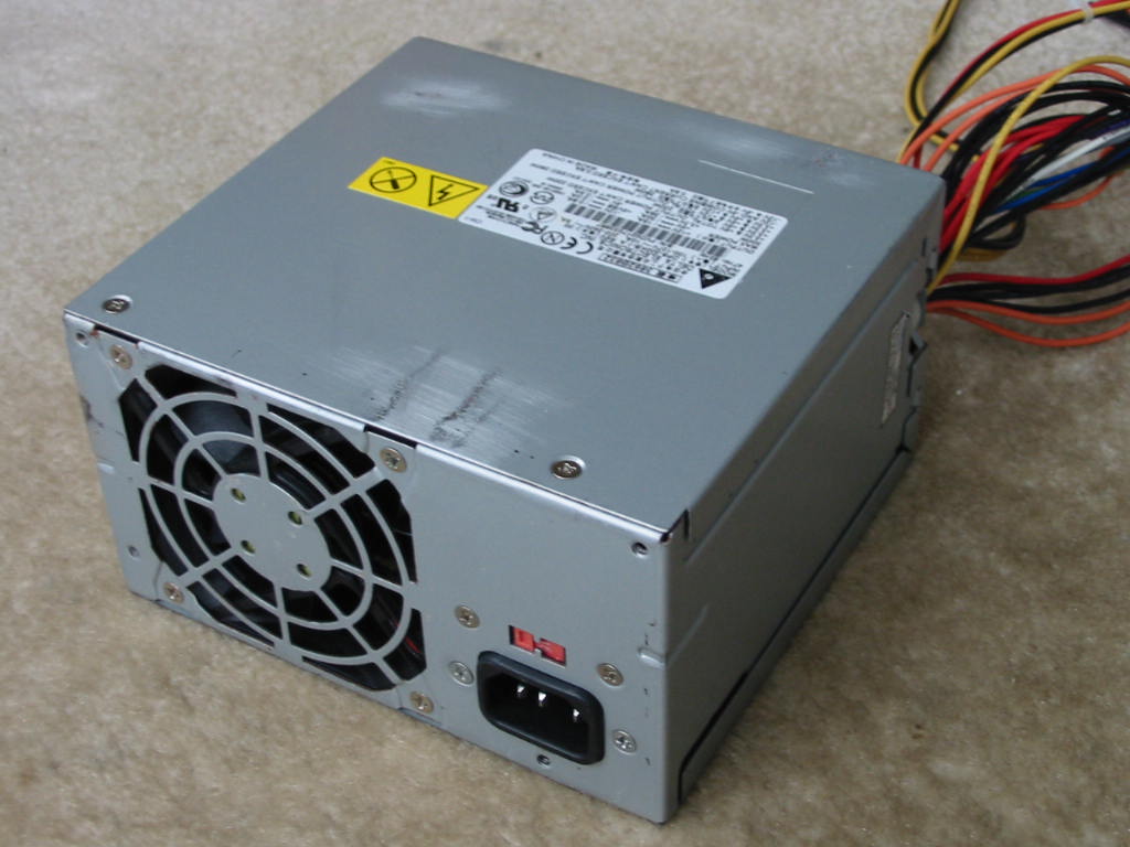


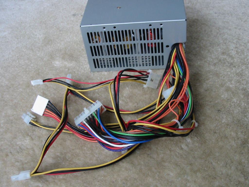
    Unit has a classic clam-shell case (with a few rust spots, as it came from a dirty warehouse PC) and thick steel. For output connectors, we have the standard: 20-pin ATX, 4-pin 12V CPU, 5x Molex drive, and 1x floppy - all done with 18 AWG, 300V wires. There is also a 3.3V AUX connector for whatever reason. Just based on the weight of the PSU and good wires, one can tell it’s a well-built PSU.

    Moving onto the label:
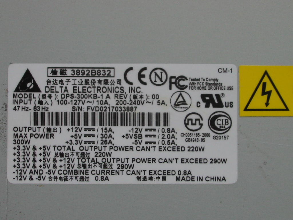
    Wow, check that 3.3V/5V combined power rating: 220 Watts of awesomesauce! I challenge anyone to find me a retro PC that couldn’t be satisfied by that 3.3V/5V rating. Meanwhile, the 12V rail is rated for a modest 15 Amps (probably enough for early era Pentium 4 PCs.)

    Anyways, let’s see what’s inside…
    https://www.badcaps.net/forum/attach...1&d=1616221145
    Heatisnks! And caps… and a 2nd PCB specifically for EMI/RFI filtering. I think I need to take it apart further to see more details.

    First, the EMI/RFI board:
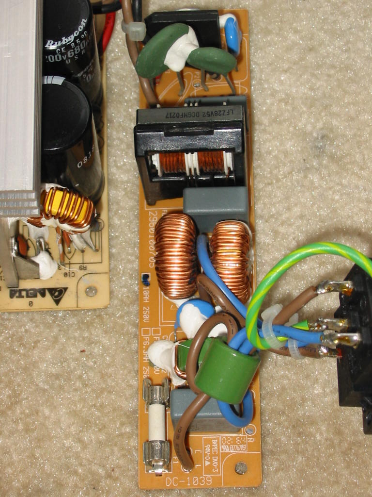
    I think Delta is literally just trying to show-off here. We have 2x CM chokes, 2x SM chokes, 3x X2 caps, and 4x Y2 caps. Also notice the fuse is in a holder and it’s a ceramic-case fuse (how it should be.) And to top it off, there are 2x NTCs. Good job, Delta!

    Now let’s look at the rest of the PSU.
    https://www.badcaps.net/forum/attach...1&d=1616221145
    https://www.badcaps.net/forum/attach...1&d=1616221145
    When it comes to good heatsinks, these older PSUs from Delta (and HiPro) from the early 2000’s are pretty much as good as they get. No wonder the PSU weights a ton. And remember, this one is rated for only 300 Watts (though IMO, these units can probably peak up to 350 Watts without problems.) The transformer and output inductors are also quite big. And on the output side, we see quite a few 12.5 mm caps, which is always nice when it comes to recapping these PSUs (which, BTW, tend to suffer from bad caps a lot less frequently than the newer units.)

    Anyways, here is the primary side:
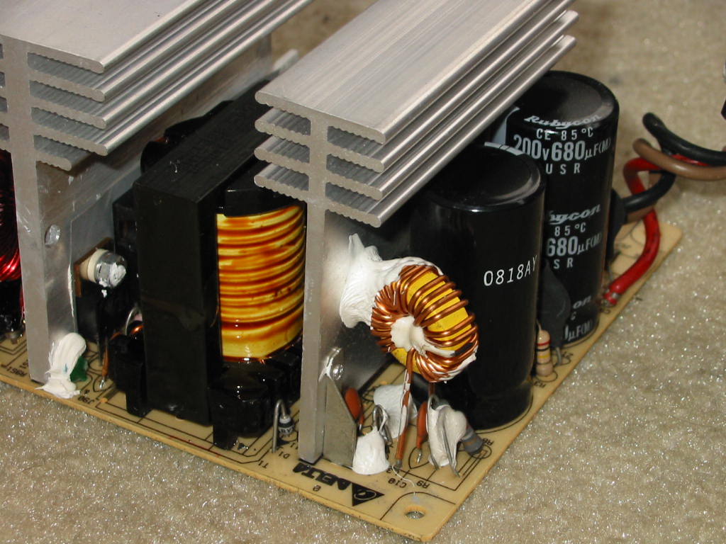
    Input caps are 2x 200V, 680 uF Rubycon USR units - more than adequate for the power rating of this PSU. The little toroid inductor in the corner suggests this is a single-transistor forward design. Though not visible in the above picture, there are 2x 2SK2654 MOSFETs in TO-247 cases in parallel attached to that primary heatsink. Also, the main PS transformer does not use 35 mm wide core, but 39 mm - very nice!

    Next, the secondary side…
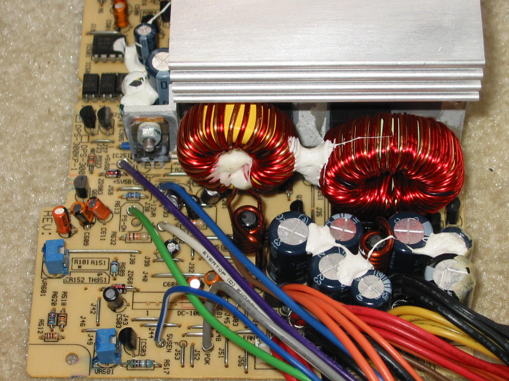
    The output caps may look small at first, but that’s only because they are dwarfed by the output filter toroids. On that note, the main PS output toroid is a T130-52 (i.e. uses Micrometals -52 core material, as the light green color with one side painted blue shows.) The 3.3V rail toroid is only slightly smaller and uses -26 core material (T103-26, I think.) All in all, very good job there. Back to the output caps… again, no less than 4 of the output caps are 12.5 mm in diameter. Now the cap choices aren’t the best - mostly Ltec LZG. However, there is a single Rubycon YXG in there on the 12V rail (I guess Delta knows where it counts, as this PSU was installed in an early P4 MicronPC that drew power primarily from the 12V rail.) Another interesting thing to notice is the “5VSEN” (5V sense) line, in addition to the standard 3.3V sense line - Delta really wanted to make sure this PSU’s 5V and 3.3V rails performed top-notch.

    What else is top notch? A yes, the soldering on the PCB:
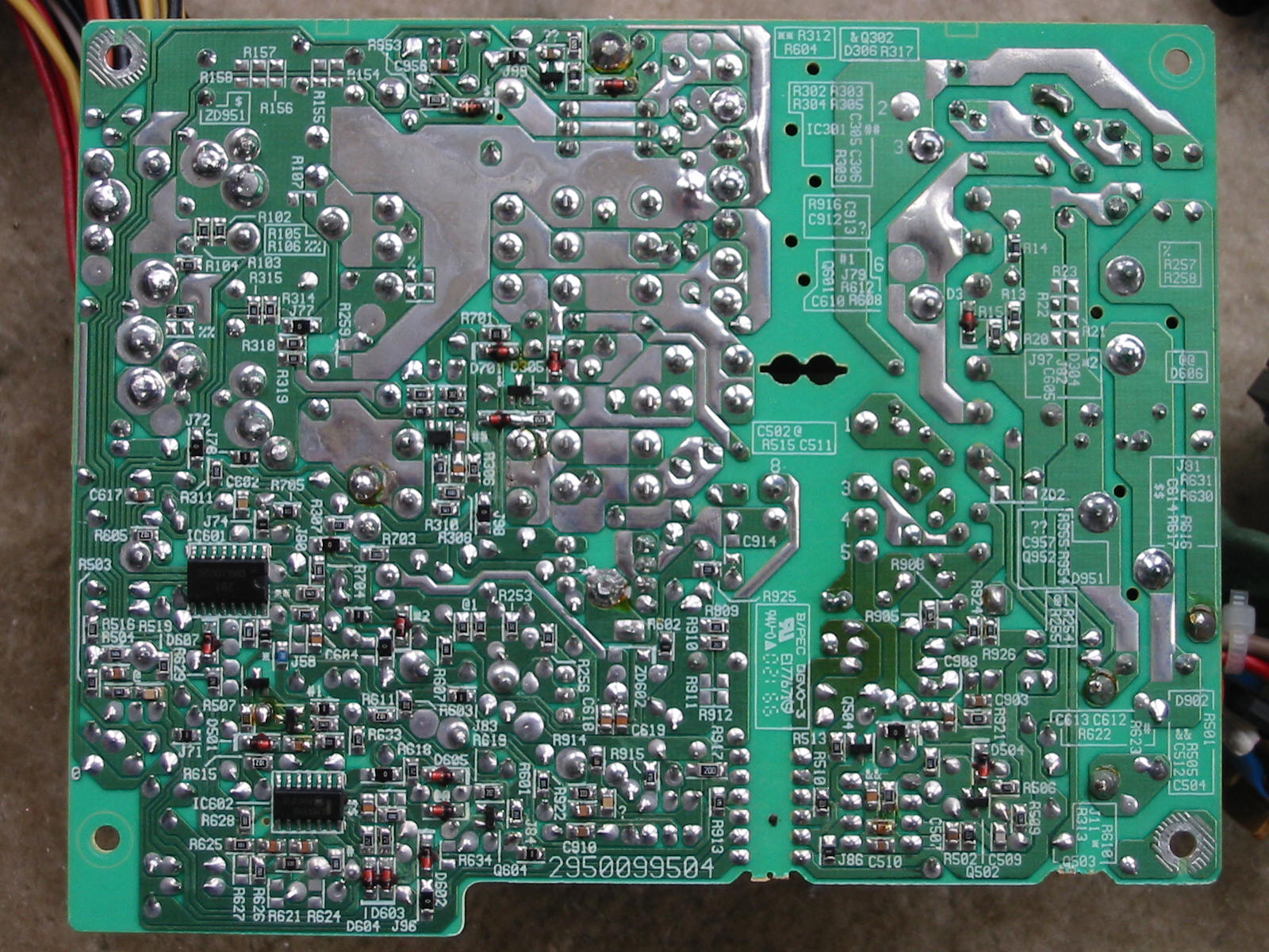

    On the above shot, however, we can see a slight darkening in the lower-right side of the board. This corresponds to the 5VSB circuit - in particular, the area right around diode D901. Here is a better shot of the top-side of the 5VSB circuit area:
    https://www.badcaps.net/forum/attach...1&d=1616221339
    The 5VSB circuit is a 2-transistor design, so users of this PSU are advised to recap the 5VSB circuit (both the output and the “critical” cap on the primary side.) From what I can tell so far, the darkening around this diode is not related to the condition of the caps, as I’ve seen the same diode with the same darkening in other Delta PSUs. In particular, it seem the diode is dissipating the most heat when the 5VSB is unloaded, even though this is not the snubber circuit diode, but rather the primary-side auxiliary rectifier (which provides power to the UC384x PWM IC and primary-side 5VSB circuitry too.) I think it has more to do with the fact that Delta used a regular 1N4001 diode here instead of a fast-recovery rectifier. On that note, for those of you who may be thinking to just swap that diode, I advise caution to be used. While I was able to successfully swap this same diode on another newer Delta PSU (with same 2-transistor 5VSB) with a FR153 part, this DPS-300KB did not appreciate the change - the 5VSB lost regulation and started producing terrible screeching noise. So I returned back the original 1N4001 diode (but with a piece of long copper braid soldered to the Cathode lead for extra heatsinking) and the 5VSB operation returned back to normal. Thus, maybe there is a reason why Delta used a 1N4001 diode here. In any case, the thing runs miserably hot with unloaded or light-loaded 5VSB, so I suggest adding a heatsink to that diode, at least.

    Last but not least, here’s a fan shot:
    https://www.badcaps.net/forum/attach...1&d=1616221339

    And that pretty much concludes all I have to say about this PSU, aside from the parts’ list below:

    ICs:
    UC3843b (PWM controller), DNA1002d (secondary-side supervisor), LM339 (secondary side protections or fan control?), and 7912 linear regulator (-12V rail)

    Wiring:
    * 600V, 18 AWG input wiring
    * 300V, 18 AWG output wiring
    * Output connectors: 20-pin ATX, 4-pin 12V CPU, 5x Molex drive, 1x floppy, 1x AUX

    Primary Side:
    * Input Filtering: three X2-class caps (2x 0.22 uF, 1x 0.1 uF), four Y2-class caps (either 2.2 nF or 3.3 nF), two CM chokes + two SM chokes
    * Input protection: F10AH250V ceramic fuse, SCK 2R512 and SCK 056 NTC inrush current limiters, 2x MOVs across each cap for voltage surge protection
    * 6 or 8 Amp (?) bridge rectifier (can’t read info due to being glued)
    * 2x Rubycon USR, 200V, 680, 22x46 mm, 85°C caps
    * P2NA60 MOSFET (TO-220) + MPS2222A BJT (TO-92) for 2-transistor 5VSB circuit
    * 1x Ltec LZG, 50V, 47 uF, 6.3x11 mm “critical” cap
    * 2x 2SK2654 MOSFETs (TO-247) in parallel for main PS
    * ERL39 main PS transformer and ERL22 5VSB transformer

    Secondary Side:
    * 5VSB
    *** 1x Ltec LZG, 6.3V, 2200 uF, 10x23 mm before PI coil (in a 12.5 mm spot)
    *** 1x Taicon PW, 10V(?), 220(?) uF, 8x13 mm after PI coil (in a spot for 5 mm LS)
    *** STPS10L40 (TO-220) rectifier

    * 3.3V Rail
    *** 2x Ltec LZG, 6.3V, 3300 uF, 12.5x20 mm with PI coil (5.5T, 5 mm core, 12 AWG wire) in between
    *** 2x STPS3045cw (TO-247) Schottky rectifiers in parallel
    *** 4x 180-Ohm SMD load resistors in parallel

    * 5V Rail
    *** 1x Ltec LZG, 6.3V, 3300 uF, 12.5x20 mm before PI coil (5.5T, 5 mm core, 12 AWG)
    *** 1x Ltec LZG, 6.3V, 2200 uF, 10x23 mm after PI coil
    *** 2x STPS3045cw (TO-247) Schottky rectifiers in parallel
    *** 4x 390-Ohm SMD load resistors in parallel

    * 12V Rail
    *** 1x Ltec LTG, 16V, 1000(?) uF, 10x20 mm and 1x Rubycon YXG, 16V, 2200 uF, 12.5x25 mm (no PI coil)
    *** 2x STPR1020ct (TO-220) Schottky rectifiers in parallel
    *** 470-Ohm ½ Watt load resistor

    * -12V Rail
    *** 1x Ltec LZG, 16V (or 25V?), 470 uF, before 7912 linear regulator (no PI coil)
    *** 1x Taicon VT, 25V, 47 uF, after 7912 linear regulator
    *** 1.5 or 2 Amp diode as rectifier

    * -5V Rail
    *** 1x Taicon VT, 50V, 10 uF, after 7905 linear regulator (input being the “raw” -12V rail before the 7912 regulator.)
    Attached Files
    Last edited by momaka; 03-20-2021, 12:24 AM.

    Comment


      Sparkle Power FSP250-60ATV

      And just as a comparison, here is a Sparkle (FSP) power supply from the same era as the Delta above. This one is the 250 Watt FSP250-60ATV.


      Again, we have a fairly heavy PSU here with similar cabling to the Delta: 20-pin ATX, 4-pin 12V CPU, 5x Molex drive, 2x floppy, and 1x AUX, all done with 300V, 18 AWG wiring (except for the minor rails on the ATX connector.) This PSU also came out of another dirty warehouse computer (and a MicronPC again), hence the rust spots on the case.

      Next, a shot of the label:

      Despite this being only a 250 Watt PSU, the ratings on the rails aren't that much lower than the Delta: only 20 Amps on the 3.3V rail vs. 26 and 27 Amps on the 5V rail vs. 30. The 12V rail is similar too, being rated at ~13 Amps and probably good enough for an early Pentium 4 rig. While the combined 3.3V/5V power rating is not as high as on the DPS-300KB above, it's still no slouch either at 175 Watts combined. So even this PSU should be enough for any retro 5V-heavy dual-CPU rig one can throw at it.

      Now let's look inside the case. (No overall shot this time, though.)


      https://www.badcaps.net/forum/attach...1&d=1616221694

      Again, the heatsinks are not something to dismiss here. Although they may not be as big as the ones in the Delta PSU above, they are still hefty enough for the power on the label. The primary one has a cut on it for a PPFC choke. Sadly, this PSU did not come with a PPFC choke installed. The bridge rectifier and input filter caps also aren't as big, and neither is the input EMI filtering as impressive as the one in the Delta. However, all of the parts here are still perfectly adequate for the rated power. The main difference between this PSU and the Delta is the topology: here we have the classic H-bridge again, as indicative by the three transformers in the middle… which by the way, are ERL35 for the main PS, EE16 for the BJT drive, and EE16 for the 5VSB. The two TO-220 parts mounted on the primary heatsink are 13009 NPN BJTs. As for the 5VSB, it's a 2-transistor design again, with its main transistor (4N60b MOSFET in TO-220 isolated case) mounted on a separate smaller heatsink. Unlike the Delta DPS-300KB, this 5VSB circuit does not appear to have a “critical” cap on the primary side. So the only things to worry about are the output caps.

      Speaking of output, here is the secondary side:
      https://www.badcaps.net/forum/attach...1&d=1616221694
      https://www.badcaps.net/forum/attach...1&d=1616221694
      Despite this PSU having the same case size and PCB size as the Delta, somehow the component layout looks more cluttered, yet the PSU “packs” smaller components. Add on top of this the infamous tan glue that goes brown and conductive over time (and an annoyance to remove), and I can see why people don't like to deal with (recap) these PSUs. The dummy load resistors also require a bit of modding, since the original ones tend to run very hot and often cook the PCB around them, along with any nearby components. In fact, after a few minutes of running, I could smell a strong hot glue scent coming from this PSU, right from the area near the dummy load resistors. But if one can get over the tan glue and resistor mods, these PSUs are still worth recapping, IMO. I haven't recapped this particular one yet, though I've recapped a slightly newer 400W version (to be posted another time) and it's been a reliable PSU so far. The original caps in this Sparkle are mostly a mix of OST RLP with a few CapXon and Teapo here and there. Output toroid inductors both have Micrometals -26 cores, which should be adequate, given the PSU uses half-bridge. I'm not sure about their size, but if I had to guess, they are both likely T103-26. Also, an interesting note: the PWM controller + supervisor IC is one of those FSP custom jobbies, labeled “FSP 3528 332”. And of course, you can see there is a fan controller on a separate PCB mounted on the secondary heatsink (which makes things easier if one wants to do any mods to change the fan speed of the PSU.)

      Right, now let's see the solder side of this PSU.

      Well, the soldering isn't terrible here… but it's not as pretty as the Delta one either.
      And again, we can see some darkened heat spots on the PCB, mainly under the dummy load resistors on the lower left side and also a little bit on the primary side under the area for the 5VSB circuit. I have yet to test the output caps on the 5VSB… though if they have started to go, that would certainly explain the heat around the 5VSB circuit (or it could be just an inefficient 5VSB circuit by design, I don't know yet.)

      And let's finish, once more, with a fan shot.
      https://www.badcaps.net/forum/attach...1&d=1616221694
      It's pretty much the same ADDA fan as the one in the Delta PSU, and both spinning well in both PSUs. This Sparkle PSU was actually very dusty inside when I found it, so it definitely has done a lot of hours.

      Now let's have us a detailed component list, as usual.

      ICs:
      “FSP 3528 332” (PWM controller + supervisor)

      Wiring:
      * 600V, 18 AWG input wiring
      * 300V, 18 AWG output wiring (except minor rails on ATX connector.)
      * Output connectors: 20-pin ATX, 4-pin 12V CPU, 5x Molex drive, 2x floppy, 1x AUX

      Primary Side:
      * Input Filtering: three X2-class caps (1x 0.33 uF, 1x 0.47 uF, 1x 0.1 uF), three Y2-class caps (3.3? nF), three CM chokes
      * Input protection: T6.3AL 250V glass fuse (heatshrinked), 15sp 2R58A NTC inrush current limiter, 2x MOVs across each cap for voltage surge protection
      * RS406(?) bridge rectifier
      * 2x OST SPS, 200V, 470, 22x36 mm, 85°C caps
      * 4N60b MOSFET (TO-220) + 2sc945 BJT (TO-92) for 2-transistor 5VSB circuit
      * 2x E13009 NPN BJTs (TO-220) in half-bridge configuration for main PS
      * ERL35 main PS transformer, EE16 BJT driver transformer, EE16 5VSB transformer

      Secondary Side:
      * 5VSB
      *** 1x OST RLP, 10V, 1000 uF, 10x15 mm with PI coil (4 mm core, 27 turns, 20 AWG)
      *** 3 Amp (Schottky?) diode for rectification
      *** 47-Ohm 3 Watt load resistor

      * 3.3V Rail
      *** 2x OST RLP, 10V, 3300 uF, 10x25 mm with PI coil (6 mm air core, 14 turns, 14 AWG)
      *** 1x STPS3045cw (TO-247) Schottky rectifier
      *** 8.2-Ohm 3 Watt load resistor

      * 5V Rail
      *** 1x OST RLP, 10V, 1000 uF, 10x15 mm before PI coil (6 mm core, 6 turns, 14 AWG)
      *** 1x OST RLP, 10V, 3300 uF, 10x25 mm after PI coil
      *** 1x SPR3045ct (TO-247) Schottky rectifier
      *** 10-Ohm 3 Watt load resistor

      * 12V Rail
      *** 1x CapXon GL, 16V, 3300 uF, 12.5x35 mm with PI coil before cap (5 mm core, 20 turns, 14 AWG)
      *** 1x SR1660 (TO-220) rectifier
      *** 100-Ohm 2 Watt load resistor

      * -12V Rail
      *** 1x Teapo __, 16-25(?) V, 100-220(?) uF, 6.3x11 mm with PI coil before it

      * -5V Rail
      *** Same arrangement as -12V rail above
      Attached Files

      Comment


        Re: Power supply build quality pictorial. part 2

        That Delta is interesting. The balance of 3.3V vs. 12V current and the 2A 5VSB current suggest it's from the 2000 time frame, as does the auxilliary 3.3V connector (the 24-pin ATX connector wasn't defined yet). However, the "0818" on the input caps apparently indicates it was built in 2008. That it was built in China rather than Thailand means it was a fairly high volume model. My WAG is that it's an off-the-shelf, anybody can buy it, model rather than a custom model for a particular customer, and it turned out to be very popular.
        PeteS in CA

        Power Supplies should be boring: No loud noises, no bright flashes, and no bad smells.
        ****************************
        To kill personal responsibility, initiative or success, punish it by taxing it. To encourage irresponsibility, improvidence, dependence and failure, reward it by subsidizing it.
        ****************************

        Comment


          Re: Power supply build quality pictorial. part 2

          That DPS-300KB-1A is designed very well EXCEPT for the standard recovery diode on the primary side (and you thought the toasty output diode on the +5VSB rail was a shoddy design in later units...). If it dissipates the most heat under light load or whilst unloaded, that means during actual PSU operation, when all other rails are also active besides +5VSB and when the fan is also spinning, the diode dissipates the most heat (when the forward voltage is higher, I suppose)? If so, that’s a terribly inefficient design which dooms any “critical” capacitor there (whether Taiwanese/Chinese or Japanese) to failure. Given that it’s a single-transistor forward design I’d expect a bit better than two 10A ultrafast parts (which would be equivalent to a 14A rating in forward topology when the label touts 15A) on the +12V rail but with that heatsink and good ventilation, and a good fan controller, maybe Delta could pull the rating off.

          I doubt those Rubycon USRs are from 2008. More than likely they were already old stock at the time the PSU was manufactured (2002) so they were probably made in 2000 (possibly that’s what the “0818” datecode means - 0 is the year, 2000, 8 is the month, August, etc...).

          So I present something a tad more exceptional.... actually, it’s probably the most spectacular PSU you’ll ever see in this lifetime! It’s a Magnetek PSU from a SCSI 4x4x16x Yamaha external drive. Rather long in the tooth now being over twenty two years old. The input side features a 1A 250V fuse, one coil, one X capacitor, and three Y capacitors. The input capacitor is a Siemens (now known as TDK/EPCOS) 85°C B43835-A5476-M 47uF 450V 16mmx31.5mm capacitor.

          Also present is a General Semiconductor 1.5KE180A transient voltage suppressor and a General Semiconductor UF4005 rectifier, along with a 47uF 50V 5x11 Samwha RG “startup”? capacitor. It appears a TOPSwitch TOP225Y part is used for the primary side switcher. Besides a rather “impressive” transformer and a single SFH617A optocoupler (made by General Semi again), on the output there are two 8A 35V SMD schottky rectifiers (on the underside, B835L parts made by Motorola which obviously rely on convection cooling) for the +12V and +5V rails. Filtering the +12V rail is a 2200uF 16V Chemi-con LXF (16mmx20mm) before the ferrite coil and a 470uF 25V Chemi-con LXV (10mmx20mm) after, and filtering the +5V rail is a 1000uF 10V Chemi-con LXF (10mmx20mm) before the ferrite coil and a 220uF 25V Chemi-con LXV (8mmx15mm) after. The modular output connectors, not pictured, are 22AWG, and the fan that came with the external housing, also not pictured, is a Sunon KDE1206PTS1 (it still spins fine). I’d guess the topology is some sort of flyback design?

          I was not able to determine the actual ratings of the PSU output rails or the input rating, as Googling the model number (3830) didn’t turn up any results. Based on what similar models are rated for, I’d guess it’s a 15W PSU or something similar with a fairly modest rating on the +12V and +5V rails (something like 2A and 5A respectively).
          Attached Files

          Comment


            Re: Power supply build quality pictorial. part 2

            Originally posted by Wester547 View Post
            and you thought the toasty output diode on the +5VSB rail was a shoddy design in later units...
            I think you might be confusing me with Everell, perhaps?? At least I don't remember saying much about hot 5VSB rectifiers on the output side... or am I on the onset of amnesia here?

            Originally posted by Wester547 View Post
            If it dissipates the most heat under light load or whilst unloaded, that means during actual PSU operation, when all other rails are also active besides +5VSB and when the fan is also spinning, the diode dissipates the most heat (when the forward voltage is higher, I suppose)?
            Can't say for sure about that. When the main PS is on, the PWM controller does draw power from the primary side auxiliary rail, putting even more load on that diode... but I think that diode getting hot may also be just due to the 5VSB transformer ringing and that diode being standard recovery, taking some of the inductive kickback from the primary (despite the auxiliary and drive windings being separate). So it's possible that the load from the PWM controller may actually be decreasing the heat output. In any case, I'm surprised the 5VSB wasn't happy when I tried a fast recovery diode in there. I tried the same FR153 diode in a slightly more modern DPS-300-AB/AP, and that one took it without problems. To the naked eye, the two 5VSB circuits appear the same or at least very similar. I haven't traced a schematic for the DPS-300KB-1A, but I did do one for the DPS-300-AB, and it's a bog-standard 5VSB circuit. In fact, this 5VSB circuit from the HEC Orion HP585d is an almost identical copy of the DPS-300-AB, save for one or two resistors maybe. I haven't posted the DPS-300-AB/AP schematic here because I don't think I've posted the DPS-300-AB/AP PSU yet, either. I guess that's another one for my "to do" list for this thread.

            Originally posted by Wester547 View Post
            If so, that’s a terribly inefficient design which dooms any “critical” capacitor there (whether Taiwanese/Chinese or Japanese) to failure.

            Fortunately, the output caps typically tend to go first in these units, especially if they are CapXon or the newer Ltec (the DPS-300KB-1A is an older model with older Ltec, so these seem to last longer somehow.)

            Originally posted by Wester547 View Post
            Given that it’s a single-transistor forward design I’d expect a bit better than two 10A ultrafast parts (which would be equivalent to a 14A rating in forward topology when the label touts 15A) on the +12V rail but with that heatsink and good ventilation, and a good fan controller, maybe Delta could pull the rating off.
            Yeah, I noted that too.

            And indeed the 12V rail was quite low with a 2GHz Pentium 4 Northwood CPU, Radeon 7000 GPU, and single HDD on a Intel D845bg board both under load and idle: varying between 12.64V and 12.68V, respectively. On the other hand, you could say that was still very good performance, because the 12V rail didn't change much. And in both cases, the 5V rail was very very close to perfect spec. So I think the 12V dipping was more of a case that this PSU is better-suited for a 5V-heavy PC, as the distribution on the label would suggest.

            But whenever I get to recapping it, I might end up swapping those dual 10 Amp FR rectifiers for something like a 20 Amp Schottky. Will have to see how that PSU does with a heavy 5V load first, though - if the the 12V rail goes too high with a high 5V load, then using a Schottky on the 12V may not be a good idea. IDK, we will see when I get to it another day.

            Originally posted by Wester547 View Post
            I doubt those Rubycon USRs are from 2008. More than likely they were already old stock at the time the PSU was manufactured (2002) so they were probably made in 2000 (possibly that’s what the “0818” datecode means - 0 is the year, 2000, 8 is the month, August, etc...).

            Agreed.
            The DPS-300KB-1A should be an early 2000's PSU. The Intel D845bg motherboard, which came with the MicronPC... and which this Delta PSU also came with... is from late 2003 or early 2004 era most likely. So I imagine the PSU is from around then too. 2005 is when the Northwoods gave way to the Prescotts and PSUs with slightly beefier 12V rail and weaker 5V rail configurations started turning up.

            Originally posted by Wester547 View Post
            So I present something a tad more exceptional.... actually, it’s probably the most spectacular PSU you’ll ever see in this lifetime! It’s a Magnetek PSU from a SCSI 4x4x16x Yamaha external drive. Rather long in the tooth now being over twenty two years old.
            That is a rather unique-looking PSU... and certainly well-made.
            Reminds me of the countless number of open-frame PSUs I picked up from my last job that were getting discarded: lots of MeanWell's, TDK's, IDP (Integrated Power Designs), and PhiHong's - all well-made with good caps, just like this Magnatek PSU.

            Originally posted by Wester547 View Post
            I’d guess the topology is some sort of flyback design?
            Most definitely, it is.

            Flyback design usually (if not always?) doesn't have an output toroid, so that's one way to tell. This is also why the outputs have such large caps, yet the current capability isn't that high. If this was a regular ATX (continuous-mode) PSU, a 2200 uF and 470 uF cap on the 12V rail could easily provide decent filtering for up to 15 Amps of output. But with flyback, you can get maybe 3-4 Amps tops before the ripple starts surfacing a bit high.

            Originally posted by Wester547 View Post
            I was not able to determine the actual ratings of the PSU output rails or the input rating, as Googling the model number (3830) didn’t turn up any results. Based on what similar models are rated for, I’d guess it’s a 15W PSU or something similar with a fairly modest rating on the +12V and +5V rails (something like 2A and 5A respectively).
            If I had to guess, I'd say it's probably rated for 2-2.5 Amps on the 12V rail (with peak at 3-3.5A) and 1.5-2 Amps on the 5V rail (with peak up to 2.5A probably.) After all, this was for an external optical drive, and a lot of older optical drives were rated for about 2 Amps on the 12V rail and 1-2 Amps on the 5V rail... Thus, I think this PSU is probably capable of at least 12x2 + 5x2 = roughly 35 Watts of output power, if not 40W. Seems about right, given the construction. Could probably supply up to 50W for a few short moments without any adverse effects. Overall, really nice PSU.

            By the way, I'm presuming you took it out of that external drive just to take pictures of it... or are you planning to use it in a different project?
            Last edited by momaka; 03-26-2021, 10:40 PM.

            Comment


              Re: Power supply build quality pictorial. part 2

              Originally posted by momaka View Post
              I think you might be confusing me with Everell, perhaps?? At least I don't remember saying much about hot 5VSB rectifiers on the output side... or am I on the onset of amnesia here?
              Sorry, I wasn't addressing you and I didn't word that well. I just meant that it would behoove the reader to note however often later Delta units would cook CrapXons and LTECs by way of thermally inefficient output rectifiers on the +5VSB rail, this design is much more perturbing.

              Can't say for sure about that. When the main PS is on, the PWM controller does draw power from the primary side auxiliary rail, putting even more load on that diode... but I think that diode getting hot may also be just due to the 5VSB transformer ringing and that diode being standard recovery, taking some of the inductive kickback from the primary (despite the auxiliary and drive windings being separate).
              I have a couple of venerable Newton Powers which emit that ringing noise from the transformer once I trick them into turning on with the paper clip. I guess that means the standard recovery diode dissipates the most heat neither when the PSU is “soft-off” nor when the computer is fully loaded - it may vary with the duty cycle and the load of the computer, regardless of fan operation.

              Most definitely, it is.

              Flyback design usually (if not always?) doesn't have an output toroid, so that's one way to tell. This is also why the outputs have such large caps, yet the current capability isn't that high. If this was a regular ATX (continuous-mode) PSU, a 2200 uF and 470 uF cap on the 12V rail could easily provide decent filtering for up to 15 Amps of output. But with flyback, you can get maybe 3-4 Amps tops before the ripple starts surfacing a bit high.
              I suppose it's feasible to achieve a higher current capability in flyback topology, but it would mandate a very large output filter with incredibly sized output capacitors, probably not economically realistic to assemble a PSU of that nature on a mass scale, hence the preferability of other topologies. CRTs use flyback topology as well, but I guess they don't have as tight a tolerance for ripple specs and their flyback transformers are under different stresses and so fail more often (along with LCDs?).

              If I had to guess, I'd say it's probably rated for 2-2.5 Amps on the 12V rail (with peak at 3-3.5A) and 1.5-2 Amps on the 5V rail (with peak up to 2.5A probably.) After all, this was for an external optical drive, and a lot of older optical drives were rated for about 2 Amps on the 12V rail and 1-2 Amps on the 5V rail... Thus, I think this PSU is probably capable of at least 12x2 + 5x2 = roughly 35 Watts of output power, if not 40W. Seems about right, given the construction. Could probably supply up to 50W for a few short moments without any adverse effects. Overall, really nice PSU.
              Only the primary switcher is heatsinked in this PSU. IIRC, the capability of the switcher depends on the rest of the components and the efficiency of the PSU. So I'm guessing it would be capable of 30W at the most.

              By the way, I'm presuming you took it out of that external drive just to take pictures of it... or are you planning to use it in a different project?
              Actually, I don't have any plans for it at the moment. But the last time it was fully assembled it still worked as a whole. Given its age that is mind blowing, and to think modern drives or even drives which are slightly newer have a tendency to drop like mayflies.

              Comment


                TDK Lambda DSP30-24 DIN rail-mount power supply

                Since we changed the theme here slightly to non-PC PSUs, here's an industrial power supply I rescued from the trash bin at my old job due to not working (at the time when found) from moisture/rain seeping into the cabinet it was installed in:


                ^ It's a TDK Lambda DSP30-24 DIN-rail mount industrial PSU, rated for 24V and 30 Watts (1.25 Amps), able to supply up to 1.3 Amps max and adjustable output voltage up to 28V max. Link to the series catalog page can be found here, for those interested:
                https://product.tdk.com/info/en/prod...ta/ps_dsp.html

                I took the two pictures above after opening the case, as I didn't want to close the PSU just for the pictures, then have to open it back up again. Here's what's inside… this time starting with a solder-side shot of the two L-connected PCB's.
                https://www.badcaps.net/forum/attach...1&d=1616988462
                https://www.badcaps.net/forum/attach...1&d=1616988462

                ^ Not much to see there – just a bunch of standard SMD parts. Perhaps the only interesting bit is the water damage to the solder mask / traces in the lower-right side of the 2nd picture above. This was, of course, after I was done washing and cleaning the PSU. You can see the bridge rectifier is surface-mounted and there are two opto-couplers for feedback.

                And here are 3 top-side component shots:


                https://www.badcaps.net/forum/attach...1&d=1616988462

                https://www.badcaps.net/forum/attach...1&d=1616988462

                Again, there isn't much to see on those pictures, due to the PSU being quite packed. But all in all, you can see the EMI/RFI has one X2-class cap and one common-mode choke. There is also a single Y2-cap in there, next to the transformer, coupling the primary negative bus to the secondary-side ground. This PSU is suitable for non-grounded applications… and in fact is rated Class-II Double Insulated, so that's why there is only one Y cap placed in such way. Fuse is standard round type, rated for 2 Amps and 250V (T2.0A250V.) There is also an NTC thermistor and MOV on the line input. Bridge rectifier is the SMD part seen on the first solder-side shot above. Primary cap is a United Chemicon KMG, 400V, 120 uF, 18x32 mm. Main switching transistor is a 2SK2699 in TO-3P case – quite an overkill, probably… but this PSU is rated for 83% typical efficiency and rated to operate in environments up to 71°C!!! So maybe not that overkill, after all. There is also a 13007 NPN BJT on the primary (Q2) and an 8-pin (PWM?) IC that I couldn't read what part number it had. So I'm not sure what kind of design this is, but it sure isn't 2-transistor. Main transformer has an EI-28 mm core, which is more than large enough. On the output-side of things, there is a FCH20A15 (20 Amp, 150V Schottky) in TO-220FP isolated case. And finally, the filtering caps are 1x United Chemicon KY, 35V, 1000 uF, 12.5x20 mm and 1x United Chemicon KY(?), 35V(?), 330(?) uF, 10x16 mm.

                So as you can see, no corners were cut on this PSU. In fact, it's made so well that after I cleaned it, washed it, and let it dry, it was back in normal working condition again, despite not working when we found it and it was still plugged in to mains. How nothing blew up, I don't know, as that's usually the outcome I see when a PSU gets water inside. Since this PSU was installed in cabinet outdoors and powering camera equipment, its function was considered “critical”. Therefore, it of course had to be swapped on the spot to restore operation as quickly as possible. For small items like this that are considered “non-serviceable” by us (and since it wasn't a failure from a factory defect, thus no warranty coverage), it meant it was destined for the scrap pile… so that's how I got it. I also have a few other similar PSUs from older decommissioned equipment that were also getting scrapped (in fact, I got a big box of them – warehouse manager was more than happy to free up space and let me take them, LOL.) So if there is any interest, I can post some of those as well.
                Attached Files

                Comment


                  Re: Power supply build quality pictorial. part 2

                  Back when mammoths roamed the earth and school cafeterias were serving the last of the frozen dinoburgers, Boschert (Computer Products) had a flyback model rated for 165W convection cooled or 180W forced air cooled. This model used a BJT (MJE13009s?) for the switch.

                  The designer, Bill V., was one of those almost incomprehensible, somewhat irascible, geniuses. Bob Boschert used to say that when Bill did a design review presentation he'd gather up the papers and his notes and close his office door for an hour to figure out what Bill had presented. I was a lowly intermediate engineering tech at the time.
                  PeteS in CA

                  Power Supplies should be boring: No loud noises, no bright flashes, and no bad smells.
                  ****************************
                  To kill personal responsibility, initiative or success, punish it by taxing it. To encourage irresponsibility, improvidence, dependence and failure, reward it by subsidizing it.
                  ****************************

                  Comment


                    Re: Power supply build quality pictorial. part 2

                    Originally posted by PeteS in CA View Post
                    Back when mammoths roamed the earth and school cafeterias were serving the last of the frozen dinoburgers, Boschert (Computer Products) had a flyback model rated for 165W convection cooled or 180W forced air cooled. This model used a BJT (MJE13009s?) for the switch.
                    I think I've seen even larger flyback PSUs in some big CRTs from the early 2000's, rated for close to 200 Watts. So it's certainly not impossible... though in CRTs TVs and monitors, most of that power draw is from the B+, which is a fairly high voltage and low current rail, so not much filtering is needed, despite the relatively high power output.

                    And regarding the frozen dinoburger comment ... when I was in high-school a little over a decade and a half ago, they still served food made with frozen mammoth meat - or so it seemed, based on the taste on some of the items we had. With enough fries and ketchup, though, we would swallow just about anything.

                    In all seriousness, the food didn't taste that bad. Though a lot of the food items were definitely made of heavily-processed stuff. But hey, anything is better than being hungry, TBH!

                    Comment


                      Delta Electronics DPS-300sb A REV:03F [PCB: DPS-300sp A]

                      And… looks like we're going to go back to regular ATX PSUs here… and back to Delta, too. Today's post features a DPS-300sb A REV:03F (based on PCB: DPS-300sp A.)


                      It almost like a deja-vu of the DPS-300KP, but then also not quite. Again, we see a clam-shell –style case. But the back vents are different. Moreover, the output connectors are a bit different too: 24-pin ATX (not 20+4 pin, BTW), 4-pin 12V CPU, 2x SATA, 5x Molex drive, and 1x floppy. Most of the wires on the 24-pin ATX and all of the wires on the 4-pin CPU connectors are 16 AWG – i.e. THICC! And in between those are a few “regular” 18 AWG, 300V wires. Really only the floppy connector uses smaller (22 AWG) wires. And just like the DPS-300KP, this one is a fairly heavy PSU too.

                      Moving onto the label:

                      Well, the 3.3V/5V combined power rating is not as impressive as on the DPS-300KP, but it's still more than enough for a retro rig at 175 Watts combined. On the other hand, the 12V rail is rated slightly better at 19 Amps. I bet it could do 20-22 Amps easily if the OCP doesn't trip, because this PSU is otherwise quite overbuilt in that area.

                      Speaking of which, let's start with an overall shot.

                      Ah, nice – it's got the same style heavy-metal heatsinks as the 300KP. Probably where most of that weight is coming from. The metal shell also has two notches for a 2nd EMI/RFI filter PCB just like the 300KP. But that wasn't installed on this PSU, because it contains all of the EMI/RFI filtering on its main PCB. And let's have a look at that:


                      There are two X2-caps, 2 common-mode chokes, and plenty of Y2 caps (6 total), so the EMI/RFI filter is more than adequate. For protection, besides the fuse, there are also 2x MOVs and 2x NTC thermistors. Regarding the latter, the NTCs are configured in a very interesting way: one of them is on the Neutral, right after the Neutral wire connection on the PCB (as it should be), but the 2nd (smaller) NTC is placed on the Neutral right before the bridge rectifier and can be bypassed by the voltage-doubler circuit's switch. Thus, when this PSU is used in a country with 120V, only the big NTC thermistor is used and the 2nd one is bypassed. On the other hand, when the PSU voltage switch is set to 230V, the 2nd NTC is not bypassed and adds a bit more resistance. My guess is Delta did this to lower the inrush current on 220/230/240V (which is higher than at 120V.) So to give the PSU slightly better efficiency, they used a slightly lower resistance NTC for the 1st one and then add a bit more resistance, as needed for 230V operation, with the 2nd NTC. Smart!

                      Next, let's have a look at what's on the rest of the primary side.

                      Main PS uses STF topology, but with two TO-247 MOSFETs in parallel. Meanwhile, the 5VSB uses a free-standing (not heatsinked) TO-220FP MOSFET. But this time, the 5VSB is not a 2-transistor self-oscillator. Instead, there is a PWM IC for it. In terms of transformers, main one is ERL35 with dimensions of 35x42x11 mm. 5VSB transformer is a bit on the small side, utilizing only a 16 mm wide core… but maybe with the PWM IC, it switches at higher frequency, so perhaps that's how it can get away with it. Not much else to see other than that. Primary bulk caps are CapXon LP instead of nice Rubycon's like in the 300KP… but there's no APFC here, so we can rest assured that even these CapXon caps on the primary should be OK for a few decades, at least.

                      Bouncing over to the secondary side…

                      … there's a lovely sight of brown CapXon caps everywhere. The two bulged ones are on the 3.3V rail, and I bet that's why this PSU was “abandoned”. Should be an easy fix. The more of these OEM PSUs I recap, the more I like them. This one should be pretty easy with the caps, as both the 3.3V and 5V rails use 2x 2200 uF caps each. Meanwhile, the 5VSB and 12V rails have 1x 16V, 1500 uF each. On that note, I would have liked to see a slightly bigger capacity cap on the 12V rail. Perhaps this is the reason for the 19 Amp rating. Otherwise everything else checks out to allow for a lot more. In fact, the “12V rectifier” consists of 2x SPTS20H100 Schottky diodes, where one of them is solely used for the forward rectification while the other is used solely for the free-wheeling. Therefore, this is not just a regular “parallel” setup, and I honestly expect the 12V rail to be capable of much more than 20 Amps (perhaps 25-30A with bigger output filter cap.) The 12V rail is coupled to the 5V rail too, so regulation and 12V-heavy cross-loading shouldn't be a problem… though I will test that eventually, after I recap the PSU. And both the 3.3V rail and 5V/12V common mode output toroids use the more efficient Micrometals -52 core material (with the main 5V/12V toroid being a T130-52, I think – i.e. 1.3” dia., which is quite big.)

                      As for the soldering…

                      What can I say again? Delta knows how to solder well, for sure.

                      Lastly, as always, is the fan.

                      Delta fan in a Delta PSU… Cool with me!

                      ~~~~~~~~~~~~~~~

                      ICs:
                      “1004CL” (PWM controller main PS, primary side), “200d6” which is NCP1200 (PWM controller 5VSB, primary side), TSM1002ds (supervisor IC, secondary side), LM339 (OCP + other protections?), LM358N (OTP + fan speed?), and 7912 linear regulator (-12V rail)

                      Wiring:
                      * input: 600V, 18 AWG, EVATOP brand
                      * output: 300V, 16 AWG (4-pin CPU and most on ATX connector) and 18 AWG
                      * Output connectors: 24-pin ATX, 4-pin 12V CPU, 2x SATA, 5x Molex drive, 1x floppy

                      Primary Side:
                      * Input Filtering: two X2-class caps (2x 0.47 uF), six Y2-class caps (2x “471” on receptacle and 4x 1.0 nF on board), two CM chokes
                      * Input protection: F8AH250V fuse, SCK 2R512 (main) and SCK 2R55A (230V operation only) NTC inrush current limiters, 2x MOVs (1x across each cap for surge protection)
                      * ”0601A” bridge rectifier (too many cryptic part number in this PS already, dammit!)
                      * 2x CapXon LP, 200V, 680, 22x42 mm, 85°C caps
                      * 2x W9NK90z MOSFETs (TO-247) in parallel for main PS
                      * 1x F3NK80z MOSFET (TO-220FP) for 5VSB
                      * 1x CapXon KM, 25, 47 uF, 5x11 mm (5VSB “startup” cap, C914… and bulging)
                      * 1x United Chemicon KMF, 25/35V, 47 uF, 6.3x11 mm (PWM IC running cap)
                      * ERL35 (35x42x11 mm) main PS transformer and EEL16 5VSB transformer

                      Secondary Side:
                      *** T130(?)-52 toroid filter for 5V/12V/-12V rails
                      *** T103(?)-52 toroid filter for 3.3V rail (3.3V rail is mag-amp regulated)

                      * 5VSB
                      *** 1x CapXon GL, 16V, 1500 uF, 10x25 mm before PI coil
                      *** 1x CapXon GL, 10V, 470 uF, 8x12 mm after PI coil
                      *** PI coil: 3 mm core, 17-turn, 22 AWG wire
                      *** SB340 or SB520 Schottky diode for rectification

                      * 3.3V Rail
                      *** 2x CapXon GL, 6.3V, 2200 uF, 10x20 mm with PI coil in between
                      *** PI coil: 4 mm core, 6.5-turn, 14 AWG wire
                      *** STPS3045cw (TO-247) Schottky rectifiers
                      *** 2x 100-Ohm ¼ W SMD load resistors in parallel

                      * 5V Rail
                      *** 2x CapXon GL, 10V, 2200 uF, 10x30 mm with PI coil in between
                      *** PI coil: 4 mm core, 6.5-turn, 12 AWG wire
                      *** STPS2045ct (TO-220) for forward rectification + STPS3045cw(?) (TO-247) for freewheeling diode
                      *** 1x 510-Ohm ¼ W SMD load resistor

                      * 12V Rail
                      *** 1x CapXon GL, 16V, 1500 uF, 10x25 mm with PI coil before it
                      *** PI coil: 6 mm core, 13-turn, 14 AWG wire
                      *** 2x STPR1020ct (TO-220) Schottky rectifiers in parallel
                      *** 2x STPS20H100 (TO-220): 1x for forward rectification and 1x for freewheeling diode

                      * -12V Rail
                      *** 1x CapXon GL, 35V, 220 uF, 8x15 mm before 7912 linear regulator (no PI coil)
                      *** 1x CapXon KM, 25V, 100 uF, 6.3x11 mm after 7912 linear regulator
                      *** BYV27-xx (2 Amp) diode rectifier
                      Attached Files

                      Comment


                        Re: Power supply build quality pictorial. part 2

                        If Delta uses the YYWW date code format the PSU is about 15 years old. Even if it hasn't been used for a couple of years someone got very decent life out of those CapXon caps. Whether good airflow or the use of lower loss -52 material, or (probably) multiple factors combined, Delta seems to get a bit better life from lesser quality output caps.
                        PeteS in CA

                        Power Supplies should be boring: No loud noises, no bright flashes, and no bad smells.
                        ****************************
                        To kill personal responsibility, initiative or success, punish it by taxing it. To encourage irresponsibility, improvidence, dependence and failure, reward it by subsidizing it.
                        ****************************

                        Comment


                          Delta Electronics DPS-300sb A REV:03F [PCB: DPS-300sp A] – recap & tests

                          Originally posted by momaka
                          The 12V rail is coupled to the 5V rail too, so regulation and 12V-heavy cross-loading shouldn’t be a problem… though I will test that eventually, after I recap the PSU.
                          Right, so I did that - the DPS-300sb indeed performed quite well with both 5V-heavy and 12V-heavy cross-load tests. Basically I ran 4 tests, with the first 2 being more 12V-heavy and the last two more 5V-heavy.
                          test #1: 6 Amps on 12V rail, 2.5 Amps on 5V rail, 2 Amps on 3.3V rail
                          test #2: 12 Amps on 12V rail, 5 Amps on 5V rail, 2 Amps on 3.3V rail
                          test #3: 1.7 Amps on 12V rail, 10 Amps on 5V rail, 2 Amps on 3.3V rail
                          test #4: 2.22 Amps on 12V rail, 20 Amps on 5V rail, 2 Amps on 3.3V rail

                          For 12V-heavy tests #1 and #2, the 12V rail on the DPS-300sb dipped a bit low at 11.85V and 11.68V respectively… but that’s still well within spec. Meanwhile, the 5V rail peaked only up to about 5.10V. Now the 5V-heavy tests #3 and #4 are more interesting. In particular, some group-regulated PSUs I’ve tested so far – even older ones that should seemingly have done better with 5V-heavy loads – would pass test #3 just about OK, but a few got out-of-spec on the 12V rail voltage with test #4. On the other hand, this Delta DPS-300sb did not have such problems at all. Here are the voltages for test #4:


                          As you can see… yes, the 5V rail started dipping a bit low at 4.87V, but was still in spec. In fact, considering this load (20 Amps) represents 80% of the maximum the 5V rail is rated for, the results are rather good. What I like even better about this PSU is how well-controlled the 12V rail was with the 5V-heavy load test, peaking at no more than 12.21V. Most off-brand PSUs I’ve tested (an Apevia 620W, a Sirtec/Task TK-930TX, and a few others) were already getting close to out-of-spec on the 12V rail on test #3. With test #4, the 12V rail on all of them went above 12.6V. In fact, the Task TK-930TX was already barely below 12.6V on test #3 and close to 13V on test #4.

                          So in a few short words, the Delta DPS-300sb did very well with cross-loading, especially considering that it’s a group-regulated PSU.

                          Of course, all of the above tests were done after the PSU was recapped. On that note, here is a cap diagram of the PSU:


                          There aren’t really that many small caps or any obscure ones, so the recap was pretty straight-forward.


                          The bulging CapXon GL 2200 uF caps on 3.3V rail were replaced with 2x Rubycon ZLH of same voltage and capacity. ZLH has pretty low ESR (especially for older PSUs), but should be OK for the 3.3V rail here, as mag-amp circuits don’t mind them as much.

                          For the 5V rail, only 1 of the 2 CapXon GL caps was changed – the 1st one. I used UCC KY series rated for 10V and 2200 uF.

                          For the 12V rail, I did a slight upgrade with a UCC KYB rated for 16V and 2200 uF.

                          For the -12V rail, I didn’t change the small 100 uF output cap on the 7912 regulator, as those rarely go bad (and even then, it’s not too big of a deal, as 78xx/79xx regulators don’t need much in the way of output caps to still regulate well.) However, I did change the input to the 7912 regulator – that is, the cap for the -12V rail labeled “raw”. Here, I used UCC KZE 25V, 470 uF, as that’s the only low-ESR 25V-rated cap I had. Otherwise, I do have plenty of choices for 16V… but because this is the input to the 7912 regulator, it is advisable to use at least 25V caps, as 16V caps may not have adequate voltage overhead.

                          Finally, the 5VSB: I replaced the first filter cap – a CapXon GL 16V, 1500 uF - with a Nichicon HN 16V, 1500 uF. It’s unnecessary to go with this kind of ultra-low ESR cap here. I just have a lot of these in stock leftover from scrap Xbox 360 motherboards, and I haven’t found a 5VSB / flyback circuit that minds the drop (upgrade?) in ESR so far. Thus, I’ve been doing it to a number of PSUs now. I didn’t change the 2nd cap in the 5VSB output filter (a CapXon GL rated for 10V and 470 uF), but the Nichicon HN should be more than enough to handle everything by itself, even if that 2nd filter cap failed.

                          Apart from the output caps above, it is strongly advisable to change the small caps on the primary side as well (labeled “PWM run cap” and “5VSB startup cap”). In my case, the PWM IC run cap was already a UCC KY, if I remember correctly. But the 5VSB startup cap was a CapXon KM and ever so slightly bulging. It still read OK on capacitance (about 43 uF), but its ESR was showing about 29 Ohms, IIRC – basically way too much for a small 5x11 mm cap. Thus, I replaced it with a UCC KY of the same voltage and capacity (25V, 47 uF.) Then there is another 50V, 47 uF cap I labeled with teal color on the cap diagram above. Not sure what this is for, but I replaced it anyways. The two small caps next to the controller (that I didn’t label on the cap diagram) are rated for 1 uF and 2.2 uF. I replaced these as well, just in case. Finally, there is also a 10 uF cap close to the fan connector that I didn’t label on the cap diagram. This cap is for filtering power going to the fan and isn’t really critical in any way. Thus, I didn’t change that one.

                          In any case, the recap above should hold up quite well for a long time. Probably the 2nd output cap on the 5V rail may need changing at some point in time, as that is the only large CapXon left (aside from the primary caps – but those should be OK for a while longer too.) I’m not too worried about it, though, as that cap is easily visible from the front vent holes on the PSU. So when I see it going bad, I’ll change it (running short on 10V, 2200 uF UCC KY caps currently, hence the “short-cut”.) Besides, more than likely I will end up using this PSU with a basic 12V-based PC. So the 5V rail shouldn’t see too much loading. Of course, no telling if plans will change and where I will use this PSU. Currently, it’s still sitting in my spare PSU stash and only used for testing. It’s really handy to have a few of these OEM Delta and HiPro PSUs around, though.

                          Also, does anyone see the slight “mod” I did in the 2nd picture of the recap above?
                          Probably doesn’t matter too much, but I made a small heatsink for the 5VSB switching transistor. I was trying to get rid of an end angle cut in an aluminum L-bracket that I needed to cut for something else. So I figured I might as well cut it a bit longer and make something useful out of it rather than end up with useless scraps. The modded heatsink is screwed onto the transistor with thermal compound, of course. And I also have it glued to the primary heatsink and 5VSB transformer with silicon glue. I mean, this won’t be a proper momaka PSU recap without any goofy meddling in there, right?

                          Originally posted by PeteS in CA View Post
                          If Delta uses the YYWW date code format the PSU is about 15 years old.
                          That sounds about right.
                          This Delta DPS-300sb came from an HP mATX tower with Windows XP stickers and what appears to have been an early socket 775 Pentium 4/D motherboard... so probably a PC from the mid-2000's. Not sure if the PSU is original to the case, but it looks like it is, based on the HP P/N stickers.

                          As far as lasting 15 years - well, I don't know if it did. I got the case from a guy on Craigslist for $5, as it seemed like a pretty decent spare mATX case to keep around. But I remember seeing the ad for it possibly up to 1 year prior to when I got it. I think the ad got taken down, and then went back up around this winter. So quite possibly, the case (and PSU) have sat in storage for more than a year. In fact, when I got the case, it was quite a bit dustier/dirtier than the pictures and even had a few mouse droppings. Thus, I definitely think it sat in storage for a while.

                          Nonetheless, I wouldn't be surprised if the caps in the PSU lasted at least 10 years. Indeed Delta knows how to make lesser brands last for a good while - or at least usually past the intended life of the PC/PSU anyways. Of course, I'm of the opinion that these PSUs can be re-used for much much longer, because they are simple and built quite well - no APFC circuit to burn primary caps after X number of years, and usually no hard-to-find "unobtanium" replacement parts, in case something does go *boom* for whatever reason... though this particular PSU did have a number of "cryptic" parts that I couldn't find datasheets for. It also has a good deal of SMD parts. This is where I like the HiPro equivalents of that age just a bit better, as they usually come with none and often have space for 12.5 mm caps on the output.
                          Attached Files
                          Last edited by momaka; 05-03-2021, 05:38 PM.

                          Comment


                            Re: Power supply build quality pictorial. part 2

                            Cooler Master V1200 (80 Plus Platinum certified)

                            Main board:
                            330uF 420V x2 + 390uF 420V primary filter (all Nichicon GG)
                            330uF 16V x6 Nichicon FPCAP before all +12V output inductors with 1000uF 16V Chemi-Con KY after each output inductor
                            3900uF 16V Rubycon ZLH before +5VSB inductor and 3300uF 6.3V Chemi-Con KY after it
                            Small electrolytic capacaitors are Rubycon YXG (mostly) or Chemi-Con KY
                            Two parallel bridge rectifiers on the primary side (cannot read type number without removing them)
                            6R125P x3 MOSFETs and C3D10060 SiC rectifier for the PFC stage with 5R199P x4 MOSFETs for the main converter
                            014N04L x8 synchronous rectifier MOSFETs for the main +12V rail

                            Output connector board:
                            All electrolytic capacitors on this board are Nichicon FPCAP
                            470uF 16V on the inputs of the +3.3V and +5V DC-DC converters
                            470uF 16V on the +12V rail (disk drive connectors)
                            560uF 6.3V x4 on each of the the +3.3V and +5V rails
                            For each of the +3.3V and +5V DC-DC converters, 4D030L x3 switching MOSFETs
                            Attached Files
                            My first choice in quality Japanese electrolytics is Nippon Chemi-Con, which has been in business since 1931... the quality of electronics is dependent on the quality of the electrolytics.

                            Comment


                              Re: Power supply build quality pictorial. part 2

                              Originally posted by japlytic View Post
                              Cooler Master V1200 (80 Plus Platinum certified)
                              YAY! Finally a newer PSU that doesn't have those pesky black-colored PCBs. In fact, those red PCBs look like someone stuck an oldschool ATI Radeon video card in there.

                              Originally posted by japlytic View Post
                              330uF 420V x2 + 390uF 420V primary filter (all Nichicon GG)
                              Nice! Good to see the primary input capacitance wasn't cut to some minimum spec value. 1050 uF split across 3 big 420V caps should allow the caps to hopefully not suffer as much from the high ripple current of the APFC stage (especially at low load - those caps should just be chillin' in there. )

                              Originally posted by japlytic View Post
                              330uF 16V x6 Nichicon FPCAP before all +12V output inductors with 1000uF 16V Chemi-Con KY after each output inductor
                              3900uF 16V Rubycon ZLH before +5VSB inductor and 3300uF 6.3V Chemi-Con KY after it
                              Small electrolytic capacaitors are Rubycon YXG (mostly) or Chemi-Con KY
                              Japanese caps? Yes please! Good to see those and not the 2nd tier brands.

                              Looks really well-built, overall. Cooler Master isn't exactly know for picking the best OEM's for their PSUs (but far from the worst, too)... though I think that applies more for their lower-end units. But this one, whoever the OEM behind it is... I like what I'm seeing.

                              With that said, I think the APFC will probably be the first to fail when it kills the primary caps... but that might not happen for probably at least 10 years, if not more, seeing how many of those caps there are on the primary and their ratings/specs.

                              Comment


                                Delta Electronics DPS-300ab-15b REV:01F [PCB: DPS-300ap-15b]

                                Don't ask how many Delta PSUs I have – probably too many. This one, model DPS-300ab-15b, I didn't actually obtain as a standalone find or “purchase”. Rather, it was the PSU that came included inside a dumpster-picked Gateway GT-5656 desktop I found back around 2014 or so (and I believe was the original PSU for that PC too.) So let's have a look and see if that looks any different.


                                The case on this one indeed looks a little different from the other Delta units that I posted. Not only that, but the output wiring also seems to better match the components in the system: that is, besides the usual 20-pin ATX connector and 4-pin 12V CPU power connector, there are also 2x SATA, 2x or 3x Molex drive, and 1x floppy. The GT-5656 PC doesn't have a floppy drive, but the floppy connector is used for a special Gateway external drive bay. And the Molex drive connectors are for the optical drive(s), which are oldschool IDE in that system, whereas the HDD(s) are SATA. Only thing I'm not sure about is why Gateway had it with a 20-pin ATX connector, as the motherboard in there (ECS MCP61PM-AM) has a 24-pin ATX connector. But I suspect perhaps Gateway just went with whatever was the cheapest, as the output cables of this Delta PSU consist mainly of 20 AWG wires… and they aren't very long either. So the PSU feels a bit like a “cheapie”. The label seemed fairly modest, though, with only 15 Amps on the 12V rail.


                                Note that there are no OEM names or internal model numbers here. Rather, the label states that it's a plain-straight Delta PSU. So perhaps Gateway just used a standard off-the-shelf unit? Either way, let's see what's inside it.


                                Well, there isn't anything much intriguing about this PSU: standard STF topology for the main PS with an oldschool 2-transistor self-oscillating 5VSB circuit. Cap choices are a mix of mostly Ltec and CapXon, with a few Taicon in there too (and Samxon for the primary filters.) The output filter toroid for the main PS 5V/12V rail isn't oversized like with some of the recently posted Delta PSUs I showed above, but should still be adequate for the task. It does use the more efficient -52 core material, after all. The only real letdown is the 12V rail's rectifier – it's a 16 Amp, 200V, fast-recovery –type rectifier. So how Delta is supposed to get 15 Amps of current out of it when the topology is single-transistor forward, I'm not quite sure about. 12-13 Amps is a more realistic number, IMO. Either way, I de-commissioned the PSU from the Gateway PC it was in, because with the stock Athlon 64 X2 6000+ CPU (89W TDP) and a Radeon HD 2400 GPU (19W TDP), the PSU was already pushing out very warm air from its exhaust when gaming on that PC. Moreover, the 12V rail was dipping a bit low at 11.6-11.7V, IIRC. So the 12V rail rectifier definitely was under some stress. However, I didn't do the decommissioning at least a year after I used the PC as-is. So all in all, the DPS-300ab-15b held up just fine. Once I swapped it out, it was sitting around mostly as a spare.

                                Anyways. Moving onto the solder side… there isn't anything special about the solder quality of the PCB either – it's just standard clean Delta work, as usual (which is always nice! )


                                And that concludes all the pictures I have of the stock PSU. No fan label shot, as I didn't normally take any back when I took these pictures (note the date of when they were taken, and thus how long I had them sit on my HDD, lol.) However, the fan in this PSU is a Delta, too – a dsb8012h to be exact, rated for 0.21 Amps at 12V.

                                ~~~~~~~ Parts Summary ~~~~~~~~

                                ICs:
                                UC3843bn (PWM controller main PS, primary side), DWA108 (supervisor IC, secondary side), LM339an (OCP + other protections?), and 7912 voltage regulator (for -12V rail)

                                Wiring:
                                * input: 600V, 18 AWG
                                * output: 300V, 20 AWG
                                * output connectors: 20-pin ATX, 4-pin 12V CPU, 2x SATA, 3x Molex drive, 1x floppy

                                Primary Side:
                                * Input Filtering: two X2-class caps (0.47 uF and 0.22 uF), six Y2-class caps (2x on receptacle and 4x on board), two CM chokes, 1 SM choke
                                * Input protection: F8AH 250V fuse, no NTC thermistor (?? ), 2x MOVs across each cap
                                * ”GBU6J” bridge rectifier
                                * 2x Samxon LP, 200V, 680, 22x45 mm, 85°C caps
                                * 1x W9NK90z MOSFETs (TO-247) for main PS
                                * 3NK60zfp MOSFET (TO-220FP) and 2N2222A BJT (TO-92) for 5VSB circuit
                                * ERL35 main PS transformer and EEL16 (??) 5VSB transformer

                                Secondary Side:
                                *** T103(?)-52 toroid filter for 5V/12V/-12V rails
                                *** toroid filter for 3.3V rail (3.3V rail is mag-amp regulated) uses -26 core material

                                * 5VSB
                                *** 1x CapXon GL, 16V, 1500 uF, 10x25 mm before PI coil
                                *** 1x CapXon GL, 16V, 680 uF, 8x20 mm after PI coil
                                *** PI coil: 3 mm core, 15-turn, 22 AWG wire
                                *** SB340 Schottky diode for rectification

                                * 3.3V Rail
                                *** 2x Ltec LZG, 6.3V, 2200 uF, 10x24 mm with PI coil in between
                                *** PI coil: 3 mm core, 6.5-turn, 18 AWG wire
                                *** STPS2045ct (TO-220) Schottky rectifier
                                *** 470-Ohm (?) SMD load resistor

                                * 5V Rail
                                *** 1x Ltec LZG, 10V, 2200 uF, 10x30 mm before PI coil
                                *** 1x CapXon GL, 10V, 1500 uF, 10x24 mm after PI coil
                                *** PI coil: 3 mm core, 6.5-turn, 18 AWG wire
                                *** two STPS2045ct (TO-220) Schottky rectifiers in parallel
                                *** 150-Ohm (?) SMD load resistor

                                * 12V Rail
                                *** 1x Ltec LZG, 16V, 680 uF, 10x16 mm
                                *** 1x CapXon GL, 16V, 1500 uF, 10x25 mm
                                *** no PI coil – only a current shunt (for OCP) between the two caps
                                *** STTH1602ct (TO-220) fast recovery rectifier

                                * -12V Rail
                                *** 1x CapXon GL, 35V, 220 uF, 8x18 mm before 7912 linear regulator (no PI coil)
                                *** 1x Taicon PW, 25V, 220 uF, 8x12 mm after 7912 linear regulator
                                Attached Files

                                Comment


                                  Delta Electronics DPS-300ab-15b REV:01F [PCB: DPS-300ap-15b] - recap & mods

                                  After decommissioning the above DPS-300ab-15b PSU from the Gateway PC that it was in, I put it on the shelf with the intention to recap it. I already knew it had a 2-transistor 5VSB design (with a “critical” cap too), so a recap was undoubtedly going to be required at some point in time. In 2018, however, I ran short on working PSUs while putting together some spare PC builds. So I installed this PSU (still with the original caps) as a “temporary” thing in a HP PC with an Athlon II X2 that I didn’t care much about (due to having some issues with the motherboard.) To say that I didn’t use this PC afterwards would be an understatement. I connected it to power maybe only twice in 2 years. Then, last fall as I was fixing up another similar PC and needed to power up the Athlon II X2 system to try some tests on it with the hardware from the other system, I of course ran into issues with this unrecapped Delta PSU. Basically, as soon as I applied power, I heard a very high-pitched squealing, whining noise. I powered off the PC, but the noise continued. At that point I was almost certain what the issue was – bad caps on the 5VSB, likely. So I unplugged the PSU almost immediately. And I was right about the problem!


                                  After so many years, I suppose those CapXon GL caps beat the Ltec to the finish line (of FAIL.) I swapped out the bulging CapXon GL, 16V, 1500 uF with a Nichicon HN, 16V, 1500 uF that I had on hand. This fixed the 5VSB squealing on the spot. Of course, I put the PSU aside again, so that this time I could finish the recap (as I had planned when I originally decommissioned the PSU.) Besides, the Ltec caps were also starting to show suspiciously increased capacitance, IIRC. So eventually I did the recap and this was the result:


                                  To understand what is going on, here is a cap diagram of the output capacitors:


                                  As you can see, I still didn’t do a 100% full recap (left the 2nd 5VSB cap and 2nd 12V rail caps with the original Taicon ones, as Taicon doesn’t seem to fail very often in Delta PSUs.) The 1st -12V rail filter cap was replaced with a recycled Taicon (from another Delta??) The 12V rail also received an “interesting” treatment: the Ltec LZG 680 uF cap was replaced with a Rubycon ZL 1200 uF cap and the CapXon GL 1500 uF cap was replaced with an Ltec LZP 2200 uF cap. Both of these were recycled parts (the Ltec I think I pulled from the 12V rail on one of the HiPro 300W units a few pages back.) But apart from these, the rest of the PSU received good caps. The 3.3V rail received 2x new Rubycon ZLH 6.3V, 2200 uF. The 5V received 1x Panasonic FC 16V, 2200 uF, 12.5 mm cap (recycled part from Vcore on a Foxconn motherboard, so best not used on higher voltages) and also a new Rubycon YXJ 10V, 2200 uF part. As for the “critical” cap on the 5VSB circuit, I don’t actually remember what I used as a replacement there or if I replaced it at all. It was a Taicon PW and measured good ESR and capacitance. So I might have left it for when I get more 25V, 100 uF caps, as I don’t have any ATM.

                                  After giving the PSU a recap, there was still one thing I wasn’t too keen about – the discoloration / PCB darkening around diode D951 on the primary side next to the 5VSB transformer. This darkening has been there ever since I took the pictures of this PSU back in 2014. In this case, D951 is the rectifying diode for the primary side auxiliary rail, which provides power to both the 5VSB feedback circuitry on the primary side and also power to the PWM controller on the primary. Like with the DPS-300KP PSU I showed, this diode is just a standard 1N4002 (not 1N4001 as I noted in the 300KP post – that’s a mistake.) I’m not sure why Delta insists on using a regular diode here (not even fast-recovery type!), though when I tried changing it in the Delta 300KP PSU, the 5VSB lost regulation and started oscillating wildly. Of course, I wanted to see if the Delta DPS-300ab-15b would do the same thing, so I tried it again – I replaced diode D951 (originally 1N4002) with an FR153 diode. What’s interesting is that the 300ab-15b did not have any problems with this change and the 5VSB circuit continued to work normally. However, even my new diode there was still running a bit too hot (though not as much as before.) Therefore, I removed it again, soldered a piece of used copper braid to the Cathode lead, and then soldered it back in the circuit. You can actually see that modification in the first recap picture I posted above (on the left side.) After doing this, the diode seemed to run a bit cooler as the copper braid was doing its job of sinking heat away from it.

                                  And speaking of the 5VSB circuit, I drew the schematic of that so I could get a better idea of what’s going on. Here it is:


                                  One interesting note for the DPS-300ab-15b 5VSB circuit is that it looks very similar on the primary side (despite me arranging the components on the schematic in a slightly different order) to that of the HEC Orion HP585D PSU I posted a while back. That said, both of these 5VSB circuits are quite power-hungry and easily waste 3-4 Watts without a load. (Well, that hot diode in the 300ab-15b has to take its power from somewhere. )

                                  Finally, I replaced the STTH1602ct fast recovery rectifier on the 12V rail with an MBR20100CT that came from the KDMPower MIPC MI-X8775CD PSU that I repaired not too long ago. That PSU can’t really provide much power anyways, so it was a bit of waste to have 2x 20 Amp Schottky rectifiers on its 12V rail, while the Delta DPS-300ab-15b was just chugging barely along with a single 16 Amp FR rectifier. You can see the “new” 12V rectifier in the Delta PSU in the 2nd recap picture above. This did actually improve the 12V rail cross-load regulation by about 0.2 to 0.3V and brought it much closer to 12V under load. So I think that was a good change.

                                  And that’s all I really have for this Delta PSU. Now cast your votes when you think I will have to open it again to change that 2200 uF Ltec LZP cap on the 12V rail.
                                  Attached Files
                                  Last edited by momaka; 05-17-2021, 07:38 PM.

                                  Comment


                                    Re: Power supply build quality pictorial. part 2

                                    I give it between a month and 6 months since you let it know you're willing to spend time on it.
                                    Don't buy those $10 PSU "specials". They fail, and they have taken whole computers with them.

                                    My computer doubles as a space heater.

                                    Permanently Retired Systems:
                                    RIP Advantech UNO-3072LA (2008-2021) - Decommissioned and taken out of service permanently due to lack of software support for it. Not very likely to ever be recommissioned again.
                                    Asus Q550LF (Old main laptop, 2014-2022) - Decommissioned and stripped due to a myriad of problems, the main battery bloating being the final nail in the coffin.


                                    Kooky and Kool Systems
                                    - 1996 Power Macintosh 7200/120 + PC Compatibility Card - Under Restoration
                                    - 1993 Gateway 2000 80486DX/50 - Fully Operational/WIP
                                    - 2004 Athlon 64 Retro Gaming System - Indefinitely Parked
                                    - Main Workstation - Fully operational!

                                    sigpic

                                    Comment


                                      Re: Power supply build quality pictorial. part 2

                                      Originally posted by kevin! View Post
                                      Here show you a PSU Dell alienware aurora r3, specifically a Newton Power/Delta electronics n875ef-00
                                      The source carries an ADDA fan.
                                      I am surprised by its design, it has hardly any transformer, does anyone know how this type of PSU works? It amazes me how it is built, I have never seen anything to it.
                                      There are LTEC capacitors, but they have 30,000h, they have not given problems, but surely change the capacitors for quality ones.
                                      Do you still own this power supply? I have one that is not working; has a blown IC. I was hoping you could help me identify this chip because mine is so badly damaged that the partnumber isnt visible anymore.

                                      Comment


                                        Re: Power supply build quality pictorial. part 2

                                        Originally posted by terradrone View Post
                                        Do you still own this power supply? I have one that is not working; has a blown IC. I was hoping you could help me identify this chip because mine is so badly damaged that the partnumber isnt visible anymore.
                                        Nevermind, i found out the partnumbers that i needed. For future reference: This is about a Dell PSU from an Alienware Aurora R4, model N875EF-00 / pcb is Newton NPS-875BP. The parts that i needed to identify where c903 and ic903. C903 seems to be a 100nf 630v 10% film capacitor. IC903 is a TNY280PN. This psu also seems to be used in the Dell Precision T5500 workstation.

                                        Comment


                                          Re: Power supply build quality pictorial. part 2

                                          Originally posted by momaka View Post
                                          Looks really well-built, overall. Cooler Master isn't exactly know for picking the best OEM's for their PSUs (but far from the worst, too)... though I think that applies more for their lower-end units. But this one, whoever the OEM behind it is... I like what I'm seeing.
                                          V series is quite nice, I've reviewed different models yeaaaars ago on HWI, looks like you haven't read Last was V650 https://www.hardwareinsights.com/coo...odular-review/ looks I have the V850 still opened and not finished for like 3 years now, shame on me
                                          Less jewellery, more gold into electrotech industry! Half of the computer problems is caused by bad contacts

                                          Exclusive caps, meters and more!
                                          Hardware Insights - power supply reviews and more!

                                          Comment

                                          Working...
                                          X