Re: Bestec....the next generation
So........are you going to fix it or is it headed for the scrap pile? If you don't mind, see if you can locate where C36 is on this particular psu. C36, C37, and a coil usually form a pi filter for the 5vsb. Also, are those two bulging capacitors in the 3.3 volt circuit, or did I misguess that one?
-
Re: Bestec....the next generation
I was wondering, because I have a client with about 50-60 of them.Leave a comment:
-
Re: Bestec....the next generation
Dunno honestly I just get them already yanked outta the machines. But yeah I'd say it was a Dell based on the single power mosfet driving it... just about every Dell PSU I have seen has the same configuration.Leave a comment:
-
Re: Bestec....the next generation
No 4 pin molex - only time I've seen PSUs without those is in Dell Vostro 200 PCs - is that what the PSU was pulled from?Leave a comment:
-
Re: Bestec....the next generation
That would be a Bestec ATX0350D5WA. Considering the fact that it has no 4 pin molex connectors and is fairly dust free on the inside I'd assume that it is no more than 1-2 years old tops if that. My bad typo... meant to say C36.
Edited to add: Its been one of those days.Last edited by Evil Lurker; 04-11-2011, 09:32 PM.Leave a comment:
-
Re: Bestec....the next generation
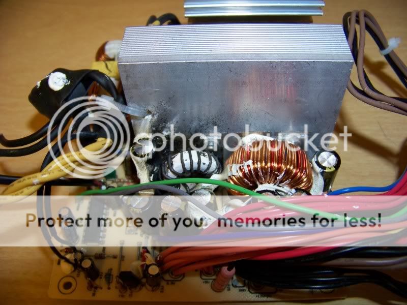
Is this a Bestec? What model?? Looks to me like the 3.3 volt line had a problem. I see two bulging capacitors and the 3.3 volt coil looks burnt.
My complaint was capacitor C36 on the other side of the heat sink. Not sure about what Q36 is.Leave a comment:
-
-
Re: Bestec....the next generation
>> Bestec....the next generation <<
Do I sense a Trekkie influence in the title?Leave a comment:
-
Re: Bestec....the next generation
Is this what happens when Q36 goes tits up?
Leave a comment:
-
Re: Bestec....the next generation
 everell, you're the best in Bestec knowledge.
Leave a comment:
-
Re: Bestec....the next generation
I know that. That 'important' cap would go bad and 5V would run away.
Starting bias is supplied through R55 and R56. Q12 starts conducting. The tertiary winding provides feedback via C3. After a few cycles, C19, C23, and C24 begin to charge up. C19 is the 'critical cap' and its rectifier is D28. Eventually, the voltage on C19 gets low enough to cause ZD2 to conduct. When that happens, drive to Q12 is removed and energy is no longer transferred to 5Vsb, AUX and tertiary. The ratio of the tertiary winding is such that just as the zener starts conducting, the AUX and preregulated 5Vsb supplies are of the proper voltage.
That's how these can regulate without an opto.
R57 is a load for D28/C19 and a return path for the zener. D31, C32, and R58 make up the snubber/damper.
In a two-transistor ckt, there is a resistor from Q12's emitter to the negative supply. Upon excessive primary current, the top of this resistor, "A," is high enough to bias the 2SC945 into conduction through resistor "B." This makes the main switcher fold back, limiting the current to that value that causes ~.7V drop across resistor "A."
When C19 gets high ESR, it can't charge fast enough. Therefore, the zener doesn't conduct and remove drive from Q12 when it should. Instead, the circuit has to 'kick harder' to get to the point where the tertiary voltage is high enough to make the zener conduct. But now AUX is 30-40 volts! Since there's a 7805 to 'regulate down' the 5Vsb in this particular supply, this continues until the 494 dies or the 7805 shorts. In those that take 5Vsb directly off the secondary, we end up with 10-15V directly into the motherboard. This is the very mechanism that makes this circuit run away.Attached FilesLeave a comment:
-
-
Re: Bestec....the next generation
Placing the diode in that configuration is rather common with 5vsb circuits. Look at diode D7 in the 5vsb circuit of the infamous Bestec mobo killer, the Bestec ATX-250 12E. This diode configuration is NOT what caused the psu to be a mobo killer, but the technique has been around a long time.Leave a comment:
-
Re: Bestec....the next generation
Looks like they're using a different mix in those output inductors. I'd like to say it's -52, but those are green with one face blue.
Do you realize that the 5Vsb diodes are 'backwards'? Look at my diagram. I left out the 4148(?) next to the rectifier as well as that SMT cap on the back of the board. Even though it's wired differently, the correct DC polarity is obtained. Almost like 'turning a circuit over' to switch from PNP to NPN transistors in the good old days.
-PaulAttached FilesLeave a comment:
-
-
Re: Bestec....the next generation
Next up is a Bestec ATX0300D5WC. More heavily oriented toward older 5 volt boards, this power supply has one 12 volt output at 19 amps and 5 volt output at 25 amps. What's new here? First, it has two SATA connectors as well as five molex connectors and one floppy connector. It has a 24 pin connector for the mother board and a four pin connector for cpu. Since it has a HP part number I am guessing that this is a OEM for an economy pc by HP. No six pin or eight pin connectors for high speed graphics cards. No LED indicator light on the back of the power supply case.
Inside the psu, what's new? The 5vsb uses a TNY276 chip. This pwm chip runs at 132 khz and has lots of nice new features. Looks like Bestec is moving away from the A6351 chip I have seen in so many of the Bestecs. Maybe the old A6351 workhorse has gone obsolete.
On the down side, capacitor C36 is bulging, as usual. Bestec needs to move that capacitor to a cooler location. If you get one of these to fix (for yourself, not for customers), you can drill two new holes and relocate the capacitor.Attached FilesLeave a comment:
-
-
Re: Bestec....the next generation
I use a jumper when troubleshooting the pc board out of the case. Once I am finished with the board, I remove the jumper and reinstall the switch wires that are still in the case as I put the pc board back in the case.
I did leave the jumper in one gutless wonder. It will probably never be used in a computer again. Computer power supplies I work on are not customer repairs for pay, just a hobby I acquired a couple of years ago.Leave a comment:
-
Re: Bestec....the next generation
Oh yes, complete with corrosion.
I usually don't replace the voltage switch with a jumper. Sure I could 'plug the hole' with the now disconnected switch, but it would technically void the UL listing. And that's for something officially listed, not something like a Deer with a file number that's not even listed.
In my big power supply, I did jump it out. In that case, it made things easier- fewer wires in the can and room for a power switch.
But in an LCD monitor, I've used 200V caps after the line rectifier to save people money. Only 120Vac here and a 400V cap would be 'wasted.'Leave a comment:
-
Re: Bestec....the next generation
As for glue damage, here is a picture of a diode in a Bestec ATX-250 12E after glue was removed.Attached FilesLeave a comment:
-
-
Re: Bestec....the next generation
After moving capacitor C36 and taking the pictures, I added a jumper wire to configure the pc board for 120 volts input. Originally I was going to recap this one AND get rid of all that white glue in the process, but after replacing that one capacitor the psu seems to be working great.
I may recap it yet, and remove the glue, but I hope that Bestec will pay attention to our power supply analysis, and learn that the position of capacitor C36 is causing a lot of premature failures. Not as spectacular as the 5vsb problems in the 12E models, but still a problem which needs to be addressed. Nearly every Bestec power supply I have opened has a bulging C36 capacitor.Leave a comment:
-
Re: Bestec....the next generation
The glue is still white!
I've got a 250- and 300-12Z here. The glue job in the 300 was disgusting. Across isolation barriers, etc, like I've mentioned before. The stuff on the output inductors was extra crispy. Light to dark brown, it just crumbled... I had to remove them to clean them well enough. The mess in the primary wasn't any better. Across a pin on the transformer and touching the 'discharge'/damper diode, it was especially crumbly.
You better remove that crap bridging those opts before there's an accident.
I go as far as removing the primary heatsink and 'reinserting' the components with those too-long leads- shorts waiting to happen. What really gets me is how these always seem to have good caps in the doubler, Rubycon, UCC, or Panasonic. Speaking of which, where are the leads to the 120/240 switch? I replace its leads, they are only #22 AL.
-PaulAttached FilesLeave a comment:
-
-
Re: Bestec....the next generation
I was not fully satisfied with the actual 5 volt output and 12 volt output, so I added a trimpot to the 5v/12v regulator circuit. Now I can tweek these two voltages. Remove smt resistor R60, drill two new holes and add a Bourns 3266W-1-503LF 50K trimpot (Digikey 3266-503LF-ND).Attached FilesLeave a comment:
-


-
So I have a cheap non working ATX PSU that I was learning to repair a decade ago. At the time, it blew the main fuse, bridger rectifier, NTC, and primary 9A 900V MOSFET. Replaced all except the MOSFET. 5VSB came back online. Then I poked around in it so much, measuring components one by one to a point I accidentally made the 5VSB circuit primary side went bang. Blown the AP8022 (Viper22A) PWM chip, along with a low resistance resistor and the PC817 opto isolator. I replaced them all.
In the process of poking around, I also lost a zener diode that stabilize the voltage coming from... -
Hi,
Finally replaced all of the shorted 4148's and resistors and an blown tl431 on my FSP300-60GTF after 5VSB going crazy and destroying it self. Those components also made the secondary transistors appear shorted (while in reality they weren't).
Powered it on through my dim bulb tester and they (bulbs) only flash once meaning primary caps are getting charged, but that's it. No 5VSB, PS_ON voltages.
I am sure I have replaced the components correctly and that there weren't any shorted/blown traces left.
Any ideas where to go next? -
 Hi to all 😎
I'm looking for any useful information to repair this interface (I have attached the image).
On this board I read E3215-1215A_4D.
This is the small plate inside the HD enclosure that allows to connect a 12 volt power supply, interface the disk with a USB 3.0 socket and is connected to the HD with the SATA connector.
If any of you have found a burnt or short-circuited component in a circuit like mine, if you have useful diagrams for the repair, or even better a description for the tests at the test points, I would be very grateful.
in particular...11-12-2024, 08:08 PM -
 Hello...
I got my self a dead CM V700 PSU, with nothing on +5vsb
I have tried to fix it for the past 2 week, and I'm stuck... so i guess i post it here to get some pointer before i scrap it..
As you can see in photo, the psu still pretty clean, no visible damage or bulging cap.. when i got it, it still has CM seal on it
The +5vsb system use ICE2QR4765, I have trace and measure the voltage on ICE2QR4765 and the only voltage reading i got is in VCC 4.8v, Drain 310v and FB 3v.
I have read the datasheet and and still can not... -
I have been wanting to do this project for some time using a Mean-well switching power supply that I bought at least ten of them that were originally in a device that was abandoned for some reason they were listed new but removed from equipment that was never used
I do not understand Mean-well the capacitor next to the voltage reference ic chip was a brand that is known for failure over time the other capacitors are brand name needless to say it got replaced before I even powered it on for the first time
I used a four USB outlet and electrical plate that is made for...
Leave a comment: