Old Pioneer Amp - Waveform explanation

Collapse
X
 
  • Time
  • Show
Clear All
new posts
  • Nevillet
    Badcaps Veteran
    • Sep 2019
    • 272
    • United Kingdom

    #1

    Old Pioneer Amp - Waveform explanation

    Hi All,

    I have been cleaning up a Pioneer A5 amplifier (C.1981) by cleaning connections, pots and switches. ESR on the electrolytics was all fine. I adjusted the bias as per the service manual to 0.31V.

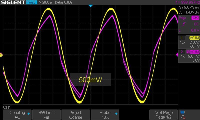
    I put a 8 ohm, 100W resistive load and and compared the channels under noticed a kind of distortion on one channel, not clipping as such, but distortion of the sine wave.

    Can anyone please explain why one channel would show this kind of distortion and where I should look for a fault.

    The screen grab shows L&R channels displaying a 1K sine wave.

    Many thanks.

    Attached Files
    Last edited by Nevillet; 01-07-2021, 03:06 PM. Reason: image not being displayed
  • petehall347
    Badcaps Legend
    • Jan 2015
    • 4426
    • United Kingdom

    #2
    Re: Old Pioneer Amp - Waveform explanation

    hope you didnt really mean 310mv ?

    Comment

    • petehall347
      Badcaps Legend
      • Jan 2015
      • 4426
      • United Kingdom

      #3
      Re: Old Pioneer Amp - Waveform explanation

      check further back in the circuit to see where its coming from .
      also try without a speaker load .
      and try without an input
      Last edited by petehall347; 01-07-2021, 05:05 PM.

      Comment

      • redwire
        Badcaps Legend
        • Dec 2010
        • 3906
        • Canada

        #4
        Re: Old Pioneer Amp - Waveform explanation

        There's three different Pioneer A-5 service manuals:
        HE, HB - Europe, UK models ART-618 but I found ART-621.
        YP, S, KC - Australia, General Export, Canada models ART-619
        KU - USA ART-617 (April 1981), ART-620.
        Circuit Description- use A-6 service manual ART-672.

        The schematics have big circuit differences. Older models used JFET Cascode with DC-coupling and servo, then changed to BJT and AC-coupling later models to lower cost. Which model do you have?

        I would say the amplifier has a problem - not a bias or offset issue. To narrow it down, I would very carefully take DC voltage measurements at the transistors and compare with the service manual's values or the other channel that works.
        For signal tracing, best with the scope set to DC coupling, trigger off the signal generator. It's difficult to troubleshoot because these are negative-feedback amplifiers which are always trying to correct for the internal problem and the scope won't easily reveal where the problem is. You could have bad capacitors because ESR is not the whole picture and I see a phase-shift (delay) between the two channels, it could be the tone controls though.

        Setting the power amplifier's bias is done with no load, good warmup and after DC offset has been checked. Across the dual emitter resistor 0.22Rx2 should have (between TP1, TP2) 31mV +/-13mV. 31mV is 70.5mA
        If you had trouble dialing that in, or it's quite unstable then problems with the bias diode. Japanese "varistor diodes" are notorious for failing in old gear. D409, D410 is STV2H, if it goes high Vf or open, bias current will go off the charts and damage the amp.
        Last edited by redwire; 01-07-2021, 08:31 PM.

        Comment

        • Nevillet
          Badcaps Veteran
          • Sep 2019
          • 272
          • United Kingdom

          #5
          Re: Old Pioneer Amp - Waveform explanation

          Hi,

          Sorry I meant 31mA. I'm trying to work out the version of A5 amp it is.

          On the solder side of the PCB there is the marking "ANV-200-0" on the component side there are no identifying marks. The serial number is "BI 9502292 S"

          The main output transistors per channel are C2579 NPN (Sanken) & A1104 PNP (Sanken)

          Also the only adjustment pots on the board are the bias controls

          Comment

          • redwire
            Badcaps Legend
            • Dec 2010
            • 3906
            • Canada

            #6
            Re: Old Pioneer Amp - Waveform explanation

            Maybe post a pic of the pc board, the newer version A-5 seems to have parts numbered transistors Q400-up, caps C400-up and the old JFET version was like C16, C17 with a few extra op-amps for servos.

            Comment

            • petehall347
              Badcaps Legend
              • Jan 2015
              • 4426
              • United Kingdom

              #7
              Re: Old Pioneer Amp - Waveform explanation

              looking like its he hb amp . its NSA . i know this design is very picky about components being changed .

              i would try and rule out the pre amp by checking wave-forms at the vol pot .

              Comment

              • Nevillet
                Badcaps Veteran
                • Sep 2019
                • 272
                • United Kingdom

                #8
                Re: Old Pioneer Amp - Waveform explanation

                Oh cr*p, I have a more immediate problem. It's started blowing the 1.25A fuse. When I power it through a variac and a series 120W lamp it lights brightly and draws 1.8A.
                The relay does not energise.
                I'll get back to it tomorrow.

                Comment

                • petehall347
                  Badcaps Legend
                  • Jan 2015
                  • 4426
                  • United Kingdom

                  #9
                  Re: Old Pioneer Amp - Waveform explanation

                  check if any outputs shorted . if so its maybe the bias trimmer went open circuit after moving it .

                  Comment

                  • Nevillet
                    Badcaps Veteran
                    • Sep 2019
                    • 272
                    • United Kingdom

                    #10
                    Re: Old Pioneer Amp - Waveform explanation

                    Hi,
                    the outputs don't appear to be shorted.
                    Measuring the current at the internal fuse it draws 480mA at 230V
                    The relay does not energise

                    Comment

                    • petehall347
                      Badcaps Legend
                      • Jan 2015
                      • 4426
                      • United Kingdom

                      #11
                      Re: Old Pioneer Amp - Waveform explanation

                      check the bias and dc offsets

                      Comment

                      • Nevillet
                        Badcaps Veteran
                        • Sep 2019
                        • 272
                        • United Kingdom

                        #12
                        Re: Old Pioneer Amp - Waveform explanation

                        Hi Pete,

                        I've reset the bias to 30 & 30 mV and the current has dropped to 100mA.

                        The only two adjustment pots on the PCB are the bias ones.

                        The DC offset on each channel is 1mV or less.

                        I am noticing that the bias voltage is wandering all over the place. If I return to it after a while it's increased significantly.

                        The relay remains un-energised.

                        Comment

                        • Nevillet
                          Badcaps Veteran
                          • Sep 2019
                          • 272
                          • United Kingdom

                          #13
                          Re: Old Pioneer Amp - Waveform explanation

                          When I momentarily turn the amp off>on the bias jumps up to around 500mV and the quiescent current to 500mA

                          Comment

                          • petehall347
                            Badcaps Legend
                            • Jan 2015
                            • 4426
                            • United Kingdom

                            #14
                            Re: Old Pioneer Amp - Waveform explanation

                            where are you measuring dc offsets ?
                            set bias after warm up .

                            Comment

                            • Nevillet
                              Badcaps Veteran
                              • Sep 2019
                              • 272
                              • United Kingdom

                              #15
                              Re: Old Pioneer Amp - Waveform explanation

                              DC offset measured at speaker outputs.

                              When the amp is warmed up and I set the bias, why would it them be so radially different following a quick on-off-on?

                              Comment

                              • petehall347
                                Badcaps Legend
                                • Jan 2015
                                • 4426
                                • United Kingdom

                                #16
                                Re: Old Pioneer Amp - Waveform explanation

                                you wont see any offsets with the relay being off ..you need to measure before the relay .i mostly look for the coils near the output transistors .

                                Comment

                                • Nevillet
                                  Badcaps Veteran
                                  • Sep 2019
                                  • 272
                                  • United Kingdom

                                  #17
                                  Re: Old Pioneer Amp - Waveform explanation

                                  We seem to back in business.
                                  The amp is working as normal.
                                  The relay engages.

                                  With the speakers disconnected and measured at the outputs, the DC offset measure 146 & 150mV.

                                  Quiescent current 150mA 230V
                                  Last edited by Nevillet; 01-12-2021, 08:14 AM.

                                  Comment

                                  • petehall347
                                    Badcaps Legend
                                    • Jan 2015
                                    • 4426
                                    • United Kingdom

                                    #18
                                    Re: Old Pioneer Amp - Waveform explanation

                                    offsets are a bit high . you could sub in a pair of transistors for each diff pair .

                                    Comment

                                    • Nevillet
                                      Badcaps Veteran
                                      • Sep 2019
                                      • 272
                                      • United Kingdom

                                      #19
                                      Re: Old Pioneer Amp - Waveform explanation

                                      Are you referring to the large power transistors (2SA1104 x2 & 2SC2579 x2)

                                      Comment

                                      • petehall347
                                        Badcaps Legend
                                        • Jan 2015
                                        • 4426
                                        • United Kingdom

                                        #20
                                        Re: Old Pioneer Amp - Waveform explanation

                                        no the differential pairs .. i think these are 5 legged ones .
                                        you can use closely matched pairs that are correct spec to do the job .

                                        Comment

                                        Related Topics

                                        Collapse

                                        • dreamlayers
                                          Weird clipping on Logitech Z-10 speakers
                                          by dreamlayers
                                          I bought used Logitech Z-10 computer speakers. They can act as a USB audio device or accept line input, and they have a headphone output jack. Some music didn't sound right, so I played a frequency sweep and heard other frequencies and beat frequencies between them and the sweep. I uploaded a spectrogram of a frequency sweep. From the very start, some but not all odd harmonics are visible, indicating symmetric distortion. Then at higher frequencies there are descending images of those harmonics, indicating non-linearity and constant higher frequency noise mixing with the harmonics. The image of...
                                          05-22-2025, 11:41 AM
                                        • Bushcat
                                          Pioneer PL-X9 motor speed control wobble
                                          by Bushcat
                                          I'm starting to re-cap a Pioneer PL-X9 turntable, specifically the motor control board, because although everything tests out OK according to the service manual, the speed wavers slightly despite the quartz lock light remaining on. So, I've decided to re-cap that board since it's the cheapest next step...

                                          Pioneer's passive component naming convention is clear to me. For example, CSZA R22M 35 is tantalum, radial leads, 0.22uF, 20%, 35V.

                                          BUT there are two capacitors on the board which have actual Pioneer part numbers: PCL-042. I can tell they are 0.1uF, 16V but don't...
                                          05-24-2023, 03:36 AM
                                        • technodruid
                                          Wavetek 130 Output issues
                                          by technodruid
                                          First post!

                                          Last night I finally got a chance to try out a wavetek 130 that I purchased a year ago or so after finally getting unpacked from a move. It was working really well, I was testing the various settings from the 50 ohm output into my rigol scope and it seemed to be fairly accurate. I was stepping through the course adjust from x10 to x100 and sweeping the dial looking for any distortions or drops/rises in amplitude. It all looked great.

                                          Then when i switched to the 1M setting, the sine wave disappeared. I moved back to x100k and the sine wave was still gone. Something...
                                          04-04-2024, 10:32 AM
                                        • EduCabral
                                          [Help Needed] Yatour YT-M06 (Pioneer 1) – Firmware or Schematic Request
                                          by EduCabral
                                          Hi everyone,

                                          I'm currently working on reviving a Yatour YT-M06 CD Changer Emulator module for use with a Pioneer 1 interface (specifically with a DEH-P5950IB head unit).

                                          While the unit is recognized as a CD changer, none of the USB, SD, or AUX features respond, which leads me to believe the firmware may be corrupted or incompatible.

                                          🔧 Details:
                                          • Model: YT-M06
                                          • Interface: Pioneer 1
                                          • MCU: Fujitsu MB89F202
                                          • Goal: Find a valid .bin firmware file or memory dump from a working unit

                                          I'm happy to attempt flashing, analyzing memory dumps, or doing hardware-level...
                                          07-15-2025, 12:26 AM
                                        • pixelcap
                                          Pioneer Kuro Pro 111FD 8 red blink error
                                          by pixelcap
                                          Pioneer Kuro Pro 111FD 8 blink red LED.


                                          I have been trying to solve the power-down 8-blink red LED problem with my Pioneer.


                                          So far I have replaced the power supply board, and the digital assembly board, I have reconnected the ribbons to all boards, ensuring the connections are good. Even though the problem is the 8 red light error and not the more common 8 blue light error code, I had Kcrownie,
                                          based in North Carolina replace the chips that cause the 8 blue LED problem (the main board and audio board) the plasma is still powering...
                                          10-06-2024, 11:26 PM
                                        • Loading...
                                        • No more items.
                                        Working...