Mic circuit for iPhone 4S.

Collapse
X
 
  • Time
  • Show
Clear All
new posts
  • JonathanAnon
    Badcaps Veteran
    • Jul 2012
    • 457
    • Ireland

    #1

    Mic circuit for iPhone 4S.

    Hi guys,

    I am building a little car kit for my iPhone. Right now, I'm working on the mic/input part of the circuit. I bought a euro store iphone handset to see what such a circuit would involve. Below is the circuit for the microphone part of that handset.


    - The push button shorts out the circuit, which answers a call.
    - I think the resistor / capacitor / diode are to filter any voltage spikes from the PB switch or possibly filter the A/C signal from the mic, but I'm unsure. ?
    - The electret mic has a resistance of 2.2K ohms.

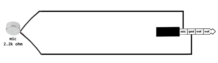
    So, if I ignore the push button for answering the call (and just use the button on the phone to answer calls), can I just hook up an electret mic of similar impedance and I'm good to go? As in this:

  • Agent24
    I see dead caps
    • Oct 2007
    • 4951
    • New Zealand

    #2
    Re: Mic circuit for iPhone 4S.

    You might need the resistor and capacitor at least for biasing the mic properly or such. I would leave them, and the diode in, if you are unsure if they should be there or not. Just omit or disconnect the button if you don't want to use it.
    "Tantalum for the brave, Solid Aluminium for the wise, Wet Electrolytic for the adventurous"
    -David VanHorn

    Comment

    Related Topics

    Collapse

    • Astonished
      Fixing the Charge Circuit of the Batteries of the DC Motor
      by Astonished
      Hi friends of electronics

      What you see in the video and pictures attached is the circuit for charging the batteries of a DC motor.

      The problem is that this circuit cannot charge the batteries (3 1800mAH NiMH batteries) any more. When the circuit was OK, its green LEDs lit up one at a time to show that the batteries have charged more. But now that the circuit is flawed, LEDs light up as you see in the video and at the same time successive beeps are heard.

      Please help me fix this circuit.

      (the datasheet of the IC: https://pdf.datasheet.live/28...
      01-28-2025, 06:24 AM
    • rddube
      Lenovo L490 Ram voltage circuit malfunction
      by rddube
      Hello friends,

      Looking for some guidance here. The RAM voltage circuit on this motherboard keeps burning out PU301 which is a RT8231AGQW. Copy of the board with the burnt chip attached with some voltage measurements and copy of the schematics also included.

      I think I've checked almost every component in the circuit, but when I change the RT8231, the laptop starts I have 1.2V on the inductor for about 10 seconds and then the RT8231 goes south and no more voltage on the inductor. All other voltages on the laptop are good, this is the only one conking out for a reason I...
      07-15-2025, 04:41 PM
    • Tarot Superstars
      Short Circuit tester
      by Tarot Superstars
      Hello.
      I have seen a short circuit tester made with 3 * 9V batteries, a voltage limiter component and a resistor connected to the probes of a multimeter.
      The theory is that the meter becomes sensitive enough to read very low resistances and the lowest resistance to ground on a circuit is likely to be a short circuit in that area.

      Link
      The Amazing $1 Short Finder Upgraded! Convert ... - YouTube
      https://www.youtube.com/watch?v=0eixDdCpiO4

      My multimeter isn't normally sensitive to very small resistance, but when I put a 1 mega ohm resistor...
      09-25-2023, 09:11 AM
    • M1NEBLANK SHOW
      MSI B250 Gaming M3 Short circuit in CPU power supply circuit
      by M1NEBLANK SHOW
      Hello. MSI B250 Gaming M3 board, short-circuit on the power supply. Found a problematic mosfet VQ1
      (N-PK616BA_PDFN8-HF) soldered it out - short circuit is gone. I replaced VQ1 + VQ5 (N-PK632BA_PDFN8-HF). VQ1 was replaced with PK618. After starting attempt VQ1 is lit again. What can be the problem? In the driver?

      Schematic and Boardview here
      ...
      04-04-2025, 03:57 PM
    • прямо
      Viper22A 5VSB circuit
      by прямо
      So I have a cheap non working ATX PSU that I was learning to repair a decade ago. At the time, it blew the main fuse, bridger rectifier, NTC, and primary 9A 900V MOSFET. Replaced all except the MOSFET. 5VSB came back online. Then I poked around in it so much, measuring components one by one to a point I accidentally made the 5VSB circuit primary side went bang. Blown the AP8022 (Viper22A) PWM chip, along with a low resistance resistor and the PC817 opto isolator. I replaced them all.

      In the process of poking around, I also lost a zener diode that stabilize the voltage coming from...
      01-13-2024, 07:05 PM
    • Loading...
    • No more items.
    Working...