Re: Fish Tank LED Power Supply Gets Hot then shuts down
So there are three aluminum heat sinks, each with 5 rows of LEDs attached with two screws. The PCBs of the LEDs are aluminum PCBs and the PCB has thermal compound grease on the aluminum side of the PCB.
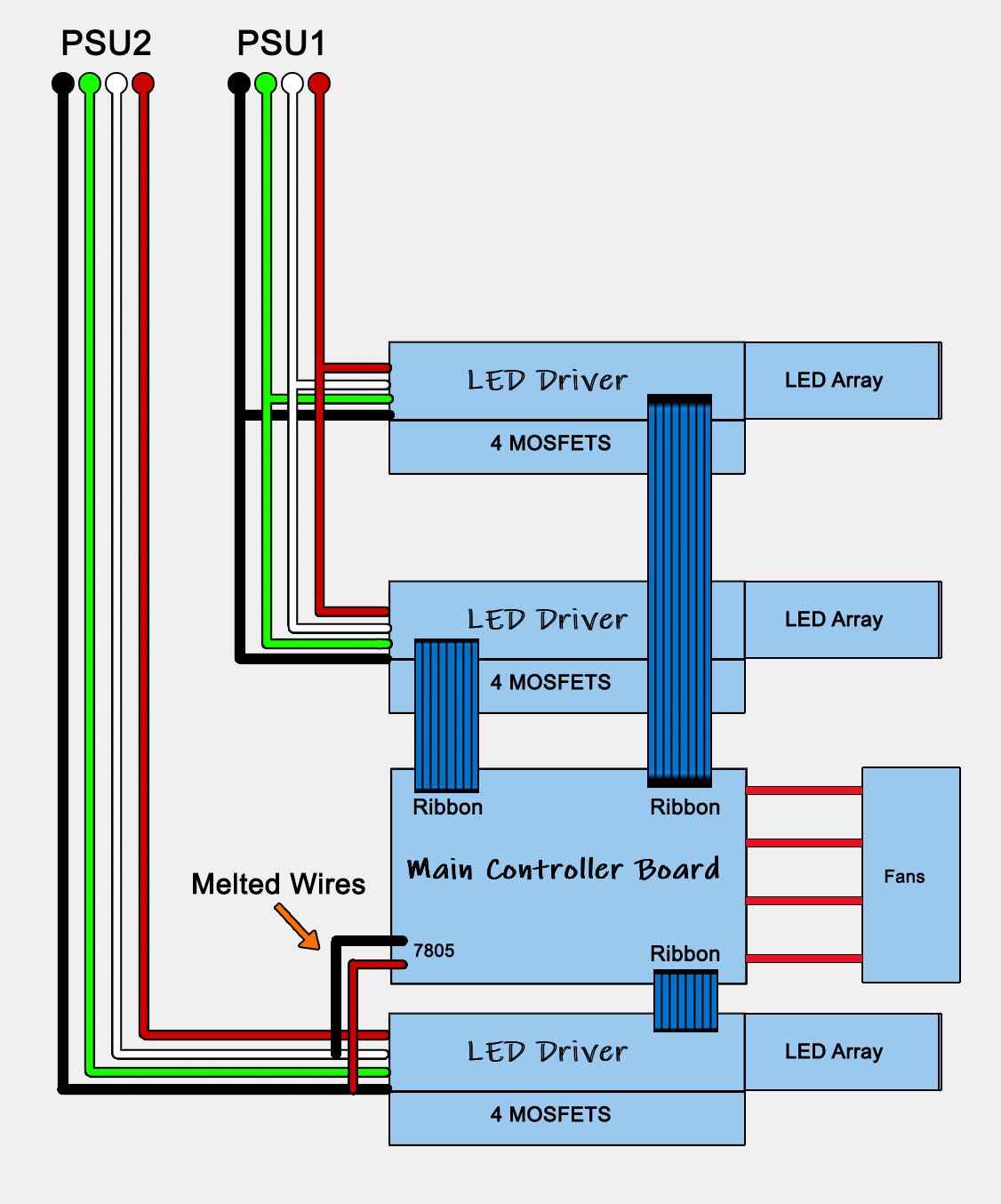
Each PCB is wired to another PCB that has high-wattage resistors on one side and the four MOSFETS on the other (which I thought was odd because there are five rows of LEDs but only four MOSFETS).
Lets call those PCBs the LED driver boards...
The PSU lines come into the unit and are soldered onto the first driver board then they are connected to the other two driver boards in a daisy chain fashion but from a schematic perspective, they would be wired in parallel.
Then from the last driver board in the housing, that 5-volt feed from the PSUs is soldered to those two wires that melted and attached to the main controller board via J3 as shown in the photos. J3 feeds the input of the 7805.
From that main controller board, there are two voltage regulators. The 7805 and a 3.3v regulator (the input of the 3.3v regulator is fed from the output of the 5v regulator), which powers the MC. There is an RS-232 chip that feeds a connector which looks like it is used to program the MC, and there is a chip that is just MOSFETS (ST TL084IN). Then two small square chips next to it (CSI 5114V) that look to be digital POTs.
The outputs from the controller board consist of the outputs that go back to each driver PCB for the lights, which are connected via ribbon cables and those would be driving the MOSFETS that power on the LEDs, then the fan outputs which each of the four fans are home run straight to the main board.
I think that MOSFET chip (TL084IN) actually drives the fans ... I don't think it has anything to do with controlling the LEDs ...
The damage to the main controller board is primarily around the 7805 and along the ground strip on the edge of the board that rides along the MOSFET chip and the digital POT chips that are next to it and that damage even managed to burn off a piece of solder mask on the board.
I checked all four fans, and three of them work. At 12 volts they are drawing 140 ma ... the fourth one does not power on at all and it is not drawing any current.
Nothing I've seen so far, explains why the 5 volt line is drawing 5.5 amps from the main PSUs ... unless there is something about those two MOSFETS on that last driver board (showing some kind of damage to them) that is the same board used to feed the 5 volt power to the controller board ... I can't rationalize how those would be in any way related electrically so Im not really sure what to think about that ... I might need to remove that board entirely and trace it out to see how things are connected but mixing that 5 volt line with those mosfets makes no sense since the mosfets drive power to the LEDs only (at least that is the assumption)
Also, the more I think about it, it makes sense to me that the small digital pots are manipulated by the MC which are then used to control the gates of the TL084IN - giving the unit the ability to control the speed of the four fans... the only thing about that is that I cannot see any kind of temperature sensor that it would use to determine how much power to give to the fans. The only temp sensor that I can see is one that sits a few mm above the microcontroller. But there might be a temp sensor on the driver boards that feed back via the ribbon cables to the MC ... but I'm not sure about that yet.
Originally posted by stj
View Post
Each PCB is wired to another PCB that has high-wattage resistors on one side and the four MOSFETS on the other (which I thought was odd because there are five rows of LEDs but only four MOSFETS).
Lets call those PCBs the LED driver boards...
The PSU lines come into the unit and are soldered onto the first driver board then they are connected to the other two driver boards in a daisy chain fashion but from a schematic perspective, they would be wired in parallel.
Then from the last driver board in the housing, that 5-volt feed from the PSUs is soldered to those two wires that melted and attached to the main controller board via J3 as shown in the photos. J3 feeds the input of the 7805.
From that main controller board, there are two voltage regulators. The 7805 and a 3.3v regulator (the input of the 3.3v regulator is fed from the output of the 5v regulator), which powers the MC. There is an RS-232 chip that feeds a connector which looks like it is used to program the MC, and there is a chip that is just MOSFETS (ST TL084IN). Then two small square chips next to it (CSI 5114V) that look to be digital POTs.
The outputs from the controller board consist of the outputs that go back to each driver PCB for the lights, which are connected via ribbon cables and those would be driving the MOSFETS that power on the LEDs, then the fan outputs which each of the four fans are home run straight to the main board.
I think that MOSFET chip (TL084IN) actually drives the fans ... I don't think it has anything to do with controlling the LEDs ...
The damage to the main controller board is primarily around the 7805 and along the ground strip on the edge of the board that rides along the MOSFET chip and the digital POT chips that are next to it and that damage even managed to burn off a piece of solder mask on the board.
I checked all four fans, and three of them work. At 12 volts they are drawing 140 ma ... the fourth one does not power on at all and it is not drawing any current.
Nothing I've seen so far, explains why the 5 volt line is drawing 5.5 amps from the main PSUs ... unless there is something about those two MOSFETS on that last driver board (showing some kind of damage to them) that is the same board used to feed the 5 volt power to the controller board ... I can't rationalize how those would be in any way related electrically so Im not really sure what to think about that ... I might need to remove that board entirely and trace it out to see how things are connected but mixing that 5 volt line with those mosfets makes no sense since the mosfets drive power to the LEDs only (at least that is the assumption)
Also, the more I think about it, it makes sense to me that the small digital pots are manipulated by the MC which are then used to control the gates of the TL084IN - giving the unit the ability to control the speed of the four fans... the only thing about that is that I cannot see any kind of temperature sensor that it would use to determine how much power to give to the fans. The only temp sensor that I can see is one that sits a few mm above the microcontroller. But there might be a temp sensor on the driver boards that feed back via the ribbon cables to the MC ... but I'm not sure about that yet.


Comment