
I have a Lenovo X1 Carbon (5th gen, 20HR, YD1KL-3, NM-B141) which beeps when power is applied. The beep code decodes to:
This is a correct assessment by the embedded controller: the NCP81218 (U137) DC/DC controller never asserts VR_RDY, which is routed to the CPU package PCH_PWROK pin.
It looks like it tries to ramp up its 1B rail, which is driven by a NCP81382 (U136).
U137's DRVON pin is routed to U136's DISB# pin; it gets driven high and stays high while power is applied.
U137's PWM_1B pin is routed to U136's PWM input. I have attached a scope trace of the PWM pin activity.
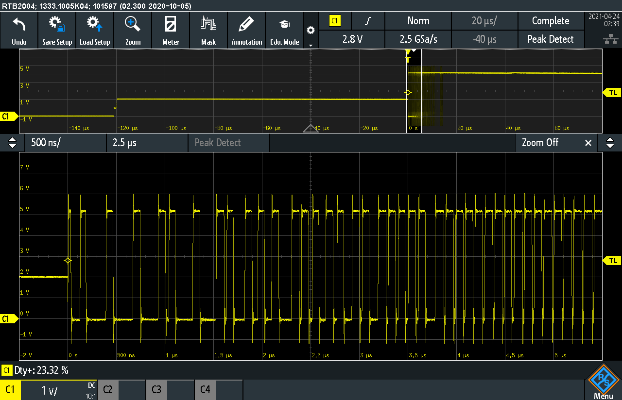
However, I don't see any activity on the output inductor, which is driven by the VSW pins. The output rail stays at 0V. All input power rails for U136 seem to be present.
The PWM pin trace matches these symptoms: after an initial mid-state voltage level (top and bottom switch open), the controller starts ramping up the duty cycle (soft start), but never reaches equilibrium and therefore drives 100% duty cycle in the end.
The output rail resistance to ground measures 25Ohms, the other output rails measure 10.4Ohms and 8.8Ohms; it seems that they are all in an acceptable range for 1V rails. Reverse (+ on ground, - on rail) measurements are 12.5Ohms, 7.4Ohms, and 6.5Ohms.
I have replaced U136, but the symptoms persist. Of course, during reflow, I might have overheated or damaged U136 so that the replacement failed in exactly the same failure mode; I don't know how likely this is though.
What could I be missing? What should I try next?
Thanks!
Attached: schematic (pages 67 & 70 relevant), similar controller datasheet, gate driver/MOSFET datasheet
0001: Reset error (platform reset not de-asserted)
This is a correct assessment by the embedded controller: the NCP81218 (U137) DC/DC controller never asserts VR_RDY, which is routed to the CPU package PCH_PWROK pin.
It looks like it tries to ramp up its 1B rail, which is driven by a NCP81382 (U136).
U137's DRVON pin is routed to U136's DISB# pin; it gets driven high and stays high while power is applied.
U137's PWM_1B pin is routed to U136's PWM input. I have attached a scope trace of the PWM pin activity.
However, I don't see any activity on the output inductor, which is driven by the VSW pins. The output rail stays at 0V. All input power rails for U136 seem to be present.
The PWM pin trace matches these symptoms: after an initial mid-state voltage level (top and bottom switch open), the controller starts ramping up the duty cycle (soft start), but never reaches equilibrium and therefore drives 100% duty cycle in the end.
The output rail resistance to ground measures 25Ohms, the other output rails measure 10.4Ohms and 8.8Ohms; it seems that they are all in an acceptable range for 1V rails. Reverse (+ on ground, - on rail) measurements are 12.5Ohms, 7.4Ohms, and 6.5Ohms.
I have replaced U136, but the symptoms persist. Of course, during reflow, I might have overheated or damaged U136 so that the replacement failed in exactly the same failure mode; I don't know how likely this is though.
What could I be missing? What should I try next?
Thanks!
Attached: schematic (pages 67 & 70 relevant), similar controller datasheet, gate driver/MOSFET datasheet
Attached Files


Comment