Re: Smasung SyncMaster 913N Monitor wouldnot display images
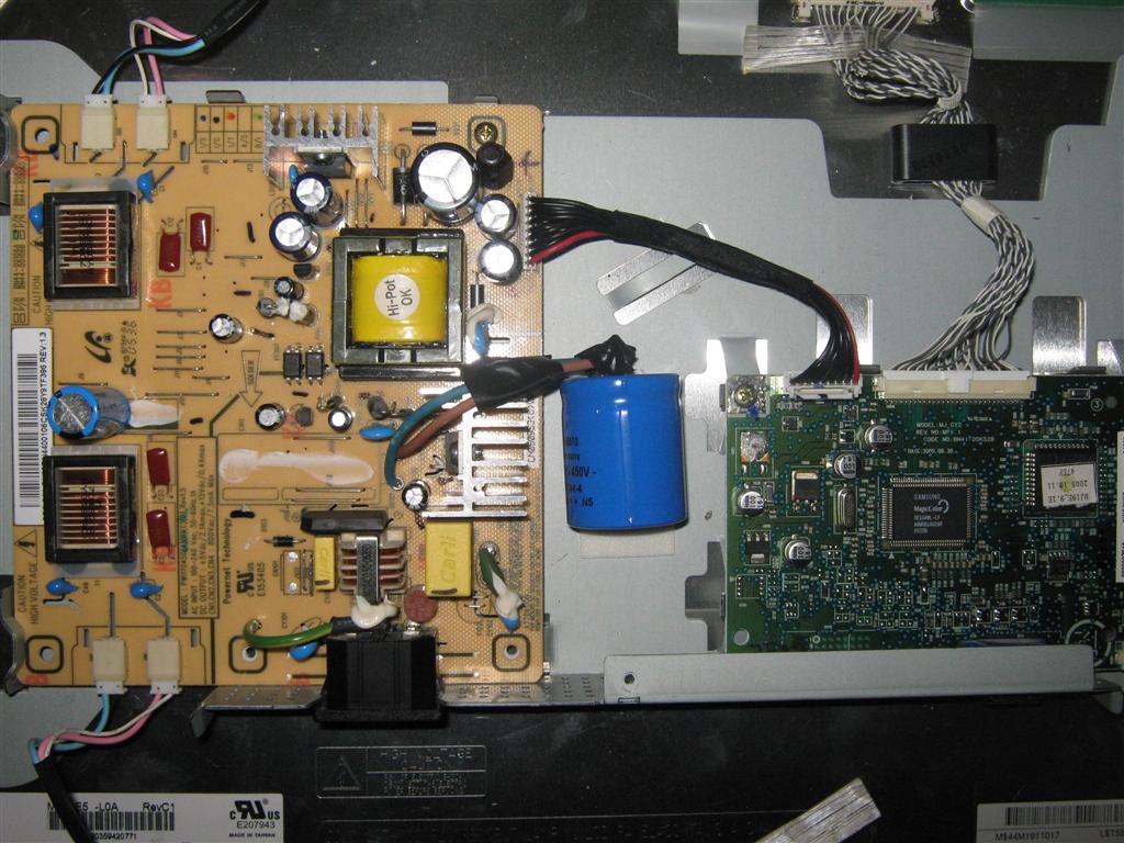

Now that's a BIG BOY ....
Another one saved from the landfill ..... good job.
Now that's a BIG BOY ....
Another one saved from the landfill ..... good job.
 )
)
 )
)
Comment