Announcement

Collapse
No announcement yet.

cicero lcd inverter IC replacment needed

Collapse
X
 
  • Filter
  • Time
  • Show
Clear All
new posts

    #21
    Re: cicero lcd inverter IC replacment needed

    Originally posted by truename
    Where did you get the AO4606? I need a few of those and wonder if this will work instead: http://www.newark.com/jsp/search/pro...FC-GB100000001

    Thanks...
    According to the datasheet I looked at the AO4606 is basically a P channel and N channel MOSFET in an IC package.

    So as long as the characteristics of the FETs are the same.

    And more importantly the pinouts are the same since one FET is P and one is N reversal of these would be an instant death for the IC.

    Compare the original ICs datasheet here:


    With the IC you are considering here:


    There is a guy on e-bay selling the original:

    http://cgi.ebay.com/AO4606-Complemen...742.m153.l1262

    Pretty pricey IMO but it's an option.
    Elements of the past and the future combining to make something not quite as good as either.

    Comment


      #22
      Re: cicero lcd inverter IC replacment needed

      Thanks Krankshaft!

      Comment


        #23
        Re: cicero lcd inverter IC replacment needed

        i am working on the same screen with the same defect powersuply board i fixed a dell 1800fp 18,1 inch screen the same way as i am trying to fix this screen its by completly removing the powerboard so if it works ill put a pinout diagram of my work
        the dell now powers up on the pc's powersuply and automaticly shuts off when i turn off the pc

        and it wont cost anything ^^
        Intel Pentium Dual Core E2200 2.2 GHz
        Asus 775 P5KPL-CM
        Asus EN9400GT Silent
        4gb ram
        Cat 32 inch monitor
        2x 500gb maxtor ide and western digital sata


        Fixed projects:
        dell 1800 fp 18,1 inch screen
        cicero lcd 17 inch screen
        hd44780 2x20(from isdn phone) lcd screen on parralel port displaying pc stats

        Comment


          #24
          Re: cicero lcd inverter IC replacment needed

          <img src="http://hjhthelag.hj.funpic.de/screen2.jpg">
          here you see the wire pinout that is on the screen i fixxed it doesnt need very good soldering and the backlight is powered by a ccfl light converter that was for modding lights(red and blue) in my acryl case so low cost for me just ripped it out and connected it works good now only you must know to not go over 1 mtr of cable for the power otherwise it wil not give any screen @ all

          greetz to all who read
          Intel Pentium Dual Core E2200 2.2 GHz
          Asus 775 P5KPL-CM
          Asus EN9400GT Silent
          4gb ram
          Cat 32 inch monitor
          2x 500gb maxtor ide and western digital sata


          Fixed projects:
          dell 1800 fp 18,1 inch screen
          cicero lcd 17 inch screen
          hd44780 2x20(from isdn phone) lcd screen on parralel port displaying pc stats

          Comment


            #25
            Re: cicero lcd inverter IC replacment needed

            Intel Pentium Dual Core E2200 2.2 GHz
            Asus 775 P5KPL-CM
            Asus EN9400GT Silent
            4gb ram
            Cat 32 inch monitor
            2x 500gb maxtor ide and western digital sata


            Fixed projects:
            dell 1800 fp 18,1 inch screen
            cicero lcd 17 inch screen
            hd44780 2x20(from isdn phone) lcd screen on parralel port displaying pc stats

            Comment


              #26
              Re: cicero lcd inverter IC replacment needed

              The 12v and 5v get its input from the PC. And the BLON signal? It is wired along the 5v (jumpered/bridged)? I've done that before but just replacing the 12v 5a input from a brick and redirecting it to the PC's output. Would be a good experiment.
              There are 10 kind of people in this world: those that understand binary, and those who don't.
              • ASUS ROG Maximus IX Code
              • Intel Core i5-7600K 3.8GHz
              • 16gb GSKILL TridentZ RGB DDR4-3200
              • 1 M2 SSD + 2 WD Blue 1TB (Mirrored)
              • Windows 10 Pro x64
              • GeForce GT1050
                2 x Acer KA240H + 1 Vewsonic VP2130 21 (a cap replacement job )

              Comment


                #27
                Re: cicero lcd inverter IC replacment needed

                no the blon and nf pins are removed, like mine or you could leave them disconected they serve no purpose in the new config becouse the board witch originaly gets 220v is completly gone

                i only had to make a switch that powers on the backlight becouse i use a ccfl power thingie from a ccfl light that was blue and red lights for case modding

                kind regards

                Jan Pierre Harmsen
                Last edited by jepezus; 05-25-2009, 07:14 AM.
                Intel Pentium Dual Core E2200 2.2 GHz
                Asus 775 P5KPL-CM
                Asus EN9400GT Silent
                4gb ram
                Cat 32 inch monitor
                2x 500gb maxtor ide and western digital sata


                Fixed projects:
                dell 1800 fp 18,1 inch screen
                cicero lcd 17 inch screen
                hd44780 2x20(from isdn phone) lcd screen on parralel port displaying pc stats

                Comment


                  #28
                  Re: cicero lcd inverter IC replacment needed

                  Hello to all!
                  This is my first post on this forum.

                  About one year ago I bought two second hand Fuljitsu-Siemens 19" LCD monitors from a friend (Scaleoview 900P).
                  I gave one to my son and one to my ex-girlfriend.
                  Both monitors just failed last week almost at the same time in a couple of days (no more power on).

                  The first one I checked was the one from my son.
                  The power board is a Mirage Electronics AD-1700 rev. F.
                  Obviously a bunch of caps (6x 470uF/25V & 1x 220uF/25V from the PSU, and the 2x 100uF/25 from the dual invertors) where screwed (bulging and even some leaking).
                  Replaced them all by Panasonic FM series low ESR capacitors and the monitor is working fine again.

                  Today I decided to have a check on my ex-girlfriend's monitor and I noticed that the PSU board is a AI-0088 instead of the AD-1700 (almost the same PCB layout).
                  This monitor started to have issues waking up from standby mode (several power off/on needed) to finally just not powering up anymore.

                  I again replaced the caps by Panasonic FM caps.
                  Weirdly I noticed that only two of the six secundary PSU caps are 470uF/25V, the other are 1000uF/25V (which unfortunately I didn't have on stock). Also the two invertor caps are 150uF/25V instead of 100uF/25V.
                  All caps seemed more or less in good condition (no obvious bulging) but I decided to replace them anyway.
                  Unfortunately the LCD still doesn't power up.
                  I also replaced the 47uF/25V near the the big 400V primary cap, still no result...

                  There are no other visible defective parts, only the PCB is a little brown around the invertors due to heat.

                  What could I check next?
                  Thanks for your input! (my ex-girlfriend has a modest income and cannot afford a new monitor at the moment...)

                  Comment


                    #29
                    Re: cicero lcd inverter IC replacment needed

                    Originally posted by Turbokeu
                    Hello to all!
                    This is my first post on this forum.

                    About one year ago I bought two second hand Fuljitsu-Siemens 19" LCD monitors from a friend (Scaleoview 900P).
                    I gave one to my son and one to my ex-girlfriend.
                    Both monitors just failed last week almost at the same time in a couple of days (no more power on).

                    The first one I checked was the one from my son.
                    The power board is a Mirage Electronics AD-1700 rev. F.
                    Obviously a bunch of caps (6x 470uF/25V & 1x 220uF/25V from the PSU, and the 2x 100uF/25 from the dual invertors) where screwed (bulging and even some leaking).
                    Replaced them all by Panasonic FM series low ESR capacitors and the monitor is working fine again.

                    Today I decided to have a check on my ex-girlfriend's monitor and I noticed that the PSU board is a AI-0088 instead of the AD-1700 (almost the same PCB layout).
                    This monitor started to have issues waking up from standby mode (several power off/on needed) to finally just not powering up anymore.

                    I again replaced the caps by Panasonic FM caps.
                    Weirdly I noticed that only two of the six secundary PSU caps are 470uF/25V, the other are 1000uF/25V (which unfortunately I didn't have on stock). Also the two invertor caps are 150uF/25V instead of 100uF/25V.
                    All caps seemed more or less in good condition (no obvious bulging) but I decided to replace them anyway.
                    Unfortunately the LCD still doesn't power up.
                    I also replaced the 47uF/25V near the the big 400V primary cap, still no result...

                    There are no other visible defective parts, only the PCB is a little brown around the invertors due to heat.

                    What could I check next?
                    Thanks for your input! (my ex-girlfriend has a modest income and cannot afford a new monitor at the moment...)
                    The first thing you should check is the batteries in your camera. Read this FAQ. Then attach pictures of the front and back of the power supply / inverter board. There are hundreds (thousands!) of models of monitors, only a few people here remember them all. I'm not one of them.

                    I'm wary of every monitor that has a 900P number, but you've already replaced the cap usually responsible. One thing to CAREFULLY test is the outputs of the power supply. The symptoms you describe are consistent with a bad power supply, but all too often we forget to go back to the basics.

                    PlainBill
                    For a number of reasons, both health and personal, I will no longer be active on this board. Any PMs asking for assistance will be ignored.

                    Never be afraid to try something new. Remember, amateurs built the ark. Professionals built the Titanic.

                    Comment


                      #30
                      Re: cicero lcd inverter IC replacment needed

                      Hi Plainbill, thanks for your reply.

                      I found a topic on this forum about the AD-1700 PSU board and the caps issue, although in my case it was obvious the caps were the culprit.

                      The only topic I found about the AI-0088 board was this one, therefore I thought posting here was a good idea.

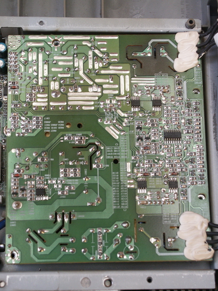
                      Some pictures of the PSU board:


                      All caps, except the big 400V one have been replaced by Panasonic FM series caps.
                      - the two 150uF/25V in the invertor section (upper half side) by 100uF/25V
                      - the 47uF/25V near the 400V cap by 47uF/50V
                      - the 220uF/25V in the secundary power supply (right side) by 220uF/25V
                      - 4x 1000uF/25V and the 2x 470uF/25V (also right side) by 6x 470uF/25V

                      Powered on the voltage on the big 400V cap is about 315VDC.
                      I'm not sure I can power on the PSU board while not attached to the logic board (directly connected through 10-pin connector CN1, 2nd picture, extreme lower right).

                      Comment


                        #31
                        Re: cicero lcd inverter IC replacment needed

                        Originally posted by Turbokeu
                        Hi Plainbill, thanks for your reply.

                        I found a topic on this forum about the AD-1700 PSU board and the caps issue, although in my case it was obvious the caps were the culprit.

                        The only topic I found about the AI-0088 board was this one, therefore I thought posting here was a good idea.

                        Some pictures of the PSU board:

                        All caps, except the big 400V one have been replaced by Panasonic FM series caps.
                        - the two 150uF/25V in the invertor section (upper half side) by 100uF/25V
                        - the 47uF/25V near the 400V cap by 47uF/50V
                        - the 220uF/25V in the secundary power supply (right side) by 220uF/25V
                        - 4x 1000uF/25V and the 2x 470uF/25V (also right side) by 6x 470uF/25V

                        Powered on the voltage on the big 400V cap is about 315VDC.
                        I'm not sure I can power on the PSU board while not attached to the logic board (directly connected through 10-pin connector CN1, 2nd picture, extreme lower right).
                        I see you didn't read the faq.

                        It would be a good idea to have the power supply hooked up the board whicl checking the voltages at CN1.

                        PlainBill
                        For a number of reasons, both health and personal, I will no longer be active on this board. Any PMs asking for assistance will be ignored.

                        Never be afraid to try something new. Remember, amateurs built the ark. Professionals built the Titanic.

                        Comment


                          #32
                          Re: cicero lcd inverter IC replacment needed

                          @PlainBill:

                          The PSU board (AI-0088) is the same as the one from the topicstarter.
                          Pictures have been resized in the meanwhile (my son borrowed the cam and I didn't realize the resolution was still set at 1600x1200), sorry for that.

                          The output voltages on connector CN1 (+5V & +12VDC) are both at 0V with the video board connected, so it seems the PSU doesn't even start.

                          I'm quite good at electronics (I'm a graduated electronic engineer since 1976) but SMPS are not my thing at all, I'm really a newbie with them (my thing is digital electronics and microcontrollers).

                          Any hint to what to check next?
                          Thanks!

                          Comment


                            #33
                            Re: cicero lcd inverter IC replacment needed

                            Originally posted by Turbokeu
                            @PlainBill:

                            The PSU board (AI-0088) is the same as the one from the topicstarter.
                            Pictures have been resized in the meanwhile (my son borrowed the cam and I didn't realize the resolution was still set at 1600x1200), sorry for that.

                            The output voltages on connector CN1 (+5V & +12VDC) are both at 0V with the video board connected, so it seems the PSU doesn't even start.

                            I'm quite good at electronics (I'm a graduated electronic engineer since 1976) but SMPS are not my thing at all, I'm really a newbie with them (my thing is digital electronics and microcontrollers).

                            Any hint to what to check next?
                            Thanks!
                            EE since 1976??? Huh!! You probably haven't worked on any REAL electronics - the stuff with vacuum tubes!!

                            I've seen LCD monitor power supplies rated for something like 5V, 3.15A. Usually they regulate the 5V supply and just let the 12V supply track (more or less). A 10 ohm resistor across the 5V output will provide sufficient load for stable operation.

                            I usually use a 'divide and conquer' approach. The first thing to check is the voltage across the large cap (typically 100uF, 450V) with the power supply connected to the monitor's logic card and AC power applied (in that order). It should read about 1.4 times AC voltage, or about 165V in the US. If that isn't present, likely causes are blown fuse, usually caused by a bad rectifier; sometimes caused by a shorted power FET.

                            If you do see the 165 volts (or whatever), you have two choices. I usually look for the data sheet for the SMPS controller (8 pin IC on the bottom of the board). Many of them show a typical application circuit. Start by checking for voltages on the SMPS controller. The other choice is to attach a 10 ohm resistor across the 5V output, just in case the problem was a shorted load. Also, check the 12V output. If the inverter is shorted, that MIGHT stop the SMPS from starting up.

                            Double check the orientation of the caps you installed. One common trap is one or more small caps by the SMPS controller. These provide startup and run power for the controller IC. If they are bad, the SMPS won't start. Many designs use a high value resistor directly from the rectified AC to charge a cap to provide start up power. Run power is from a tertiary winding on the smps transformer. These designs are very sensitive to startup load. And don't forget to check for shorted diodes on the output. It's rare, but does happen.

                            PlainBill
                            Last edited by PlainBill; 02-18-2010, 07:53 AM.
                            For a number of reasons, both health and personal, I will no longer be active on this board. Any PMs asking for assistance will be ignored.

                            Never be afraid to try something new. Remember, amateurs built the ark. Professionals built the Titanic.

                            Comment


                              #34
                              Re: cicero lcd inverter IC replacment needed

                              Originally posted by PlainBill
                              EE since 1976??? Huh!! You probably haven't worked on any REAL electronics - the stuff with vacuum tubes!!
                              Yes, since 1976 , but I never worked in electronics, always as an IT engineer.
                              During the first year of my EE studies every course was based on vacuum valves, fortunately they changed to semiconductors and TTL logic the year after.

                              I've seen LCD monitor power supplies rated for something like 5V, 3.15A. Usually they regulate the 5V supply and just let the 12V supply track (more or less). A 10 ohm resistor across the 5V output will provide sufficient load for stable operation.
                              OK, mostly like a computer power supply.

                              I usually use a 'divide and conquer' approach. The first thing to check is the voltage across the large cap (typically 100uF, 450V) with the power supply connected to the monitor's logic card and AC power applied (in that order). It should read about 1.4 times AC voltage, or about 165V in the US. If that isn't present, likely causes are blown fuse, usually caused by a bad rectifier; sometimes caused by a shorted power FET.
                              315VDC is present on the big 400V cap (230V mains here in Belgium).
                              3.15A fuse is OK.
                              Will check power FETs.

                              If you do see the 165 volts (or whatever), you have two choices. I usually look for the data sheet for the SMPS controller (8 pin IC on the bottom of the board). Many of them show a typical application circuit. Start by checking for voltages on the SMPS controller. The other choice is to attach a 10 ohm resistor across the 5V output, just in case the problem was a shorted load. Also, check the 12V output. If the inverter is shorted, that MIGHT stop the SMPS from starting up.
                              OK, will check SMPS controller voltages and try a 10 ohm load on the +5V.
                              Can I disconnect the invertors for testing?

                              Double check the orientation of the caps you installed. One common trap is one or more small caps by the SMPS controller. These provide startup and run power for the controller IC. If they are bad, the SMPS won't start. Many designs use a high value resistor directly from the rectified AC to charge a cap to provide start up power. Run power is from a tertiary winding on the smps transformer. These designs are very sensitive to startup load. And don't forget to check for shorted diodes on the output. It's rare, but does happen.
                              Orientation of the replaced caps triple checked. Unfortunately the values of the replacement Panasonic FM caps are not identical to the original values (6x 470uF instead of 4x 1000uF and 2x 470uF, and 2x 100uF instead of 2x 150uF for the invertor caps).
                              I bought all replacement caps for the AD-1700 PSU board in double, presuming the 2nd LCD monitor would have a AD-1700 board too...

                              Will also check small caps and high value resistors around the SMPS controller, and any diode present on the outputs.

                              Thanks for the hints!

                              Comment


                                #35
                                Re: cicero lcd inverter IC replacment needed

                                Hello everyone,

                                i also have a defective AI-0088 inverter. MosFET U101 roasted and some bad caps.

                                I replaced:

                                - U101 with a FDS8858CZ
                                - C101, C105 with 150uF / 35V Panasonic FM Series
                                - C011, C012 with 470uF / 25V Panasonic FM Series
                                - C020 with 220uF / 25V Panasonic FM Series

                                But i didnt have a replacement for C013, C014, C019 and C027 (1000uF / 25V / 105°C / LowESR / 10x20mm).
                                I thought about:
                                - EEUFM1E102 , but physically doesnt fit (12.5 vs. 10mm diameter)
                                - EEUFM1C102 , fits but only 16V
                                - ECA1EHG102 , fits, 1000uF / 25V / 105°C, but not LowESR

                                Is a low ESR type absolutely necessary here?

                                Btw. here is a schematic of the inverter: click

                                Comment


                                  #36
                                  Re: cicero lcd inverter IC replacment needed

                                  Originally posted by sebr View Post
                                  Hello everyone,

                                  i also have a defective AI-0088 inverter. MosFET U101 roasted and some bad caps.

                                  I replaced:

                                  - U101 with a FDS8858CZ
                                  - C101, C105 with 150uF / 35V Panasonic FM Series
                                  - C011, C012 with 470uF / 25V Panasonic FM Series
                                  - C020 with 220uF / 25V Panasonic FM Series

                                  But i didnt have a replacement for C013, C014, C019 and C027 (1000uF / 25V / 105°C / LowESR / 10x20mm).
                                  I thought about:
                                  - EEUFM1E102 , but physically doesnt fit (12.5 vs. 10mm diameter)
                                  - EEUFM1C102 , fits but only 16V
                                  - ECA1EHG102 , fits, 1000uF / 25V / 105°C, but not LowESR

                                  Is a low ESR type absolutely necessary here?

                                  Btw. here is a schematic of the inverter: click
                                  If the height isn't too high, try EEU-FC1E102L. It's 30mm high, 10mm diameter. Low ESR is required for this application.

                                  Thanks for the link to the schematic.

                                  PlainBill
                                  For a number of reasons, both health and personal, I will no longer be active on this board. Any PMs asking for assistance will be ignored.

                                  Never be afraid to try something new. Remember, amateurs built the ark. Professionals built the Titanic.

                                  Comment


                                    #37
                                    Re: cicero lcd inverter IC replacment needed

                                    thx for your answer PlainBill.
                                    The 30mm cap wont fit, only 20mm and also only 10mm diameter

                                    Hmm...i guess i will replace C019 and C014 with EEUFM1E102. Thats no problem.
                                    And for C013 and C027 i will :
                                    a) two of the old caps (lost already 30% capacity), or
                                    b) two standard caps ECA1EHG102

                                    Comment


                                      #38
                                      Re: cicero lcd inverter IC replacment needed

                                      Originally posted by sebr View Post
                                      But i didnt have a replacement for C013, C014, C019 and C027 (1000uF / 25V / 105°C / LowESR / 10x20mm).
                                      Rubycon ZLJ might meet your requirements?

                                      http://www.newark.com/rubycon/25zlj1...0uf/dp/84R1034
                                      --- begin sig file ---

                                      If you are new to this forum, we can help a lot more if you please post clear focused pictures (max resolution 2000x2000 and 2MB) of your boards using the manage attachments button so they are hosted here. Information and picture clarity compositions should look like this post.

                                      We respectfully ask that you make some time and effort to read some of the guides available for basic troubleshooting. After you have read through them, then ask clarification questions or report your findings.

                                      Please do not post inline and offsite as they slow down the loading of pages.

                                      --- end sig file ---

                                      Comment


                                        #39
                                        Re: cicero lcd inverter IC replacment needed

                                        Hi!
                                        My Iiyama Prolite E437S 17inch have the same board and failed identically
                                        to first post description. Changed mosfet and defective cap. All well know.
                                        This is a great forum. Thanks you all.

                                        Comment


                                          #40
                                          Re: cicero lcd inverter IC replacment needed

                                          One of the Mag monitors at work here won't power on this morning. I checked and the board is an AI-0088 like the one mentioned here. No noticable damage to the IC's and the caps all appear intact. How should I proceed with diagnosis from here? suggestions?

                                          Comment

                                          Working...
                                          X