LCD Display Compatibility

Collapse
X
 
  • Time
  • Show
Clear All
new posts
  • stj
    Great Sage 齊天大聖
    • Dec 2009
    • 31138
    • Albion

    #21
    Re: LCD Display Compatibility

    yes, the first 3 - all stuff you need for a running microcontroller.

    Comment

    • WHaThEFLuX
      Badcaps Veteran
      • Feb 2015
      • 277
      • USA

      #22
      Re: LCD Display Compatibility

      Ok,

      I'm getting +5V from the LM2575.

      The voltages on the Sipex are all within spec.

      I have no idea how to determine if the controller is in the reset state(something tells me this is the issue) or how to test for oscillation without a scope.

      I'll see if I can aquire a scope, in the meantime anyone have a diagram for a LED crystal checker?

      Here is the datasheet for the DS1232N, it discusses the reset function and the watchdog timer but I can't figure out how to tell if it's active!

      http://datasheets.maximintegrated.com/en/ds/DS1232.pdf
      Last edited by WHaThEFLuX; 02-01-2016, 12:33 PM.
      "You can only learn so much doing simple recapping and fixes. Ideally you want a really hard one to fix where you end up with a lot of dead ends and frustration. Then, and only then, do you learn how things really work."

      -retiredcaps

      Comment

      • eccerr0r
        Solder Sloth
        • Nov 2012
        • 8701
        • USA

        #23
        Re: LCD Display Compatibility

        I've found on the HD44780's that if the top row is darkened and the bottom row is light (and both rows not displaying anything) - it means that the display reset but no commands to initialize the display got through. But I think we already knew that. If you have a multimeter that has a Hz reading you could use that, or use your DMM if you have an AC coupling mode (perhaps just use a capacitor in series with the DMM) you could get an idea whether something is oscillating or not.

        Looks like you should check the DS1232's RST pin and make sure it's steady state low, and the !RST pin steady state high (pins 5 and 6 respectively on the DIP8).

        Comment

        • redwire
          Badcaps Legend
          • Dec 2010
          • 3912
          • Canada

          #24
          Re: LCD Display Compatibility

          Don't forget to check the LCD contrast voltage, the trimpot might be bad.
          That can cause a blank or all black display.

          Comment

          • WHaThEFLuX
            Badcaps Veteran
            • Feb 2015
            • 277
            • USA

            #25
            Re: LCD Display Compatibility

            Not sure what reading I should be getting for steady state low or high, but I do know that they read the same on the working board and the non working one.

            As for the LCD contrast voltage, should I take the reading from the solder point on the board, the pin on the display, or the trimpot itself, and how do I determine if it's good or bad?
            Last edited by WHaThEFLuX; 02-02-2016, 12:10 AM.
            "You can only learn so much doing simple recapping and fixes. Ideally you want a really hard one to fix where you end up with a lot of dead ends and frustration. Then, and only then, do you learn how things really work."

            -retiredcaps

            Comment

            • WHaThEFLuX
              Badcaps Veteran
              • Feb 2015
              • 277
              • USA

              #26
              Re: LCD Display Compatibility

              Bump, any ideas?
              "You can only learn so much doing simple recapping and fixes. Ideally you want a really hard one to fix where you end up with a lot of dead ends and frustration. Then, and only then, do you learn how things really work."

              -retiredcaps

              Comment

              • stj
                Great Sage 齊天大聖
                • Dec 2009
                • 31138
                • Albion

                #27
                Re: LCD Display Compatibility

                if you see dots on but not blured into the background i wouldnt worry about it.

                Comment

                • fzabkar
                  Badcaps Veteran
                  • Mar 2009
                  • 772
                  • Australia

                  #28
                  Re: LCD Display Compatibility

                  ISTM that the backlight voltage must be present between the PAD1 and PAD2 terminals on the PCB.

                  That said, the pinout on page 22 of the datasheet for the LCD module (DV-16230-S2FBLY-H/R22) doesn't match the pinout on the PCB (compare the VCC and VSS pins).

                  Code:
                  NO.  Symbol  Function
                  -----------------------------------------------
                  1   VCC   Power supply for Logic circuit
                  2   VSS   Ground (0V)
                  3   V0    Power Supply for Driving the LCD
                  4   RS    Data / Instruction select
                  5   R/W   Read / Write select
                  6   E    Enable signal
                  7-14 DB0-DB7 Data Bus line
                  Attached Files
                  Last edited by fzabkar; 02-02-2016, 02:42 PM. Reason: extra info

                  Comment

                  • WHaThEFLuX
                    Badcaps Veteran
                    • Feb 2015
                    • 277
                    • USA

                    #29
                    Re: LCD Display Compatibility

                    Hmm I see that, it's interesting that it works on the good board though?
                    "You can only learn so much doing simple recapping and fixes. Ideally you want a really hard one to fix where you end up with a lot of dead ends and frustration. Then, and only then, do you learn how things really work."

                    -retiredcaps

                    Comment

                    • fzabkar
                      Badcaps Veteran
                      • Mar 2009
                      • 772
                      • Australia

                      #30
                      Re: LCD Display Compatibility

                      AISI, you need to locate the VCC and VSS pins on your original and replacement modules and compare them. The heavy traces will be for power. One end of the backlight will most likely be grounded. Electrolytic capacitors would also provide a clue.

                      Comment

                      • redwire
                        Badcaps Legend
                        • Dec 2010
                        • 3912
                        • Canada

                        #31
                        Re: LCD Display Compatibility

                        What a confusing board. The PC board LCD "pin 1" (square pad) is incorrect. PCB designer has it rotated, should be on the diagonal opposite corner.

                        MCU pin 40 is Vcc with the fat trace to LCD pin 1. LCD Pin 2 GND, LCD contrast voltage pin 3.
                        LCD pin 5 has a fat trace to it, but it is the RD/WR line grounded (normal) also return for the backlight LED PAD2.

                        You can use an ohmmeter and (beep it out) see if the trimpot connects to LCD pin 3. Also LCD power pins.
                        I think 0.5V-1V there is ok for contrast. I would turn the trimpot and see if the display shows up.
                        Last edited by redwire; 02-02-2016, 08:04 PM.

                        Comment

                        • fzabkar
                          Badcaps Veteran
                          • Mar 2009
                          • 772
                          • Australia

                          #32
                          Re: LCD Display Compatibility

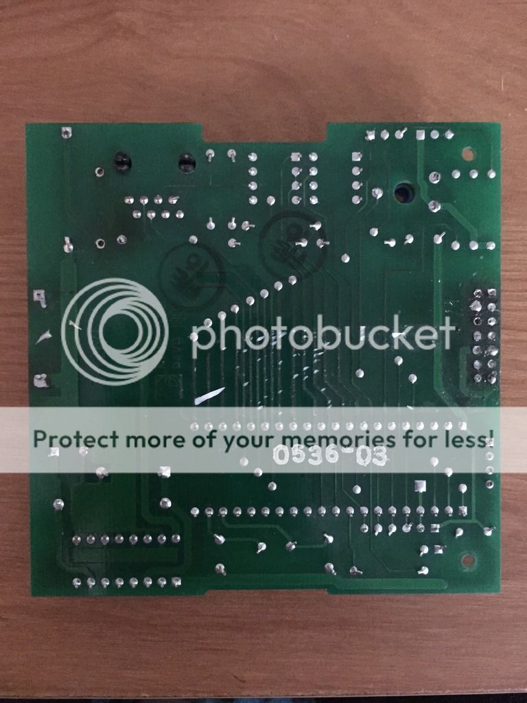
                          I would trace each of the interface pins back to the Atmel controller. Pin "5" does not look like the R/W pin to me.

                          Could we see the other side of the PCB?

                          Comment

                          • xelectech
                            retired tech
                            • Nov 2014
                            • 238
                            • USA

                            #33
                            Re: LCD Display Compatibility

                            Originally posted by redwire
                            (snip)

                            You can use an ohmmeter and (beep it out) see if the trimpot connects to LCD pin 3. Also LCD power pins.
                            I think 0.5V-1V there is ok for contrast. I would turn the trimpot and see if the display shows up.
                            Thank you sir! that bit of information makes my display (on a different thread, 'ESR meter kit') readable, after setting voltage to .3v

                            Comment

                            • WHaThEFLuX
                              Badcaps Veteran
                              • Feb 2015
                              • 277
                              • USA

                              #34
                              Re: LCD Display Compatibility

                              I won't have time to play with it today, however the trimpot is definitely connected to LCD pin 3 as well as backlight LED PAD1 and PAD2.

                              Here's a pic of the backside:

                              "You can only learn so much doing simple recapping and fixes. Ideally you want a really hard one to fix where you end up with a lot of dead ends and frustration. Then, and only then, do you learn how things really work."

                              -retiredcaps

                              Comment

                              • fzabkar
                                Badcaps Veteran
                                • Mar 2009
                                • 772
                                • Australia

                                #35
                                Re: LCD Display Compatibility

                                It looks like redwire was right on. Sorry about leading you astray.

                                Comment

                                • WHaThEFLuX
                                  Badcaps Veteran
                                  • Feb 2015
                                  • 277
                                  • USA

                                  #36
                                  Re: LCD Display Compatibility

                                  Hello all, my apologies for disappearing for a month! If anyone was curious about the answer to this project, here it is:


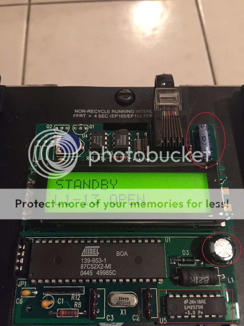
                                  The 2 capacitors and the LM2575N were the culprits, even though both capacitors seemed to be ok out of circuit. I guess when the LM2575N fried it threw them out of spec.

                                  I'd like to thank everyone for their input on this project, every time someone posts I learn something new, you guys are incredible!

                                  As it turns out this board is completely obsolete and has been replaced by a newer version which has it's fair share of problems, so if anyone wants to take a shot at my latest display issue, I'd be more than happy to post it up or make another thread!
                                  "You can only learn so much doing simple recapping and fixes. Ideally you want a really hard one to fix where you end up with a lot of dead ends and frustration. Then, and only then, do you learn how things really work."

                                  -retiredcaps

                                  Comment

                                  Related Topics

                                  Collapse

                                  Working...