Delta Electronics DPS-300KB-1 A
Another day, another Delta PSU… this time it’s an older one: DPS-300KB-1 A.
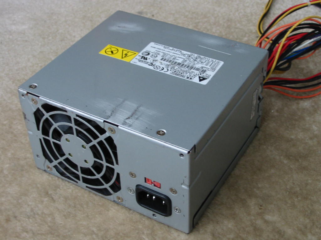
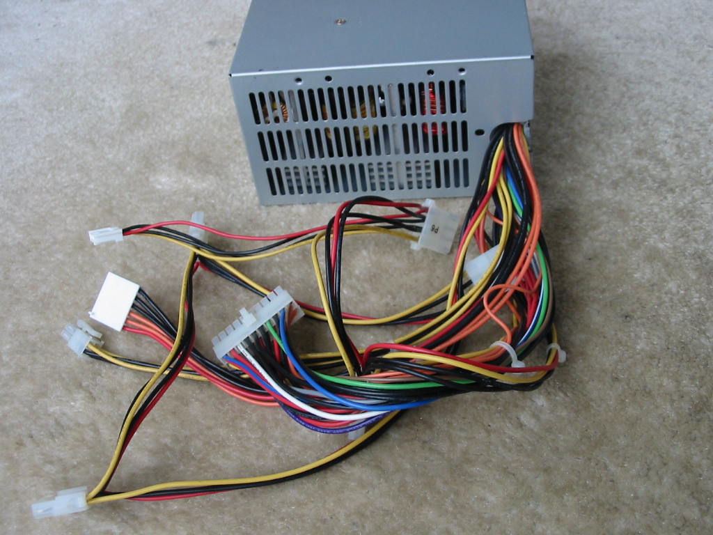
Unit has a classic clam-shell case (with a few rust spots, as it came from a dirty warehouse PC) and thick steel. For output connectors, we have the standard: 20-pin ATX, 4-pin 12V CPU, 5x Molex drive, and 1x floppy - all done with 18 AWG, 300V wires. There is also a 3.3V AUX connector for whatever reason. Just based on the weight of the PSU and good wires, one can tell it’s a well-built PSU.
Moving onto the label:
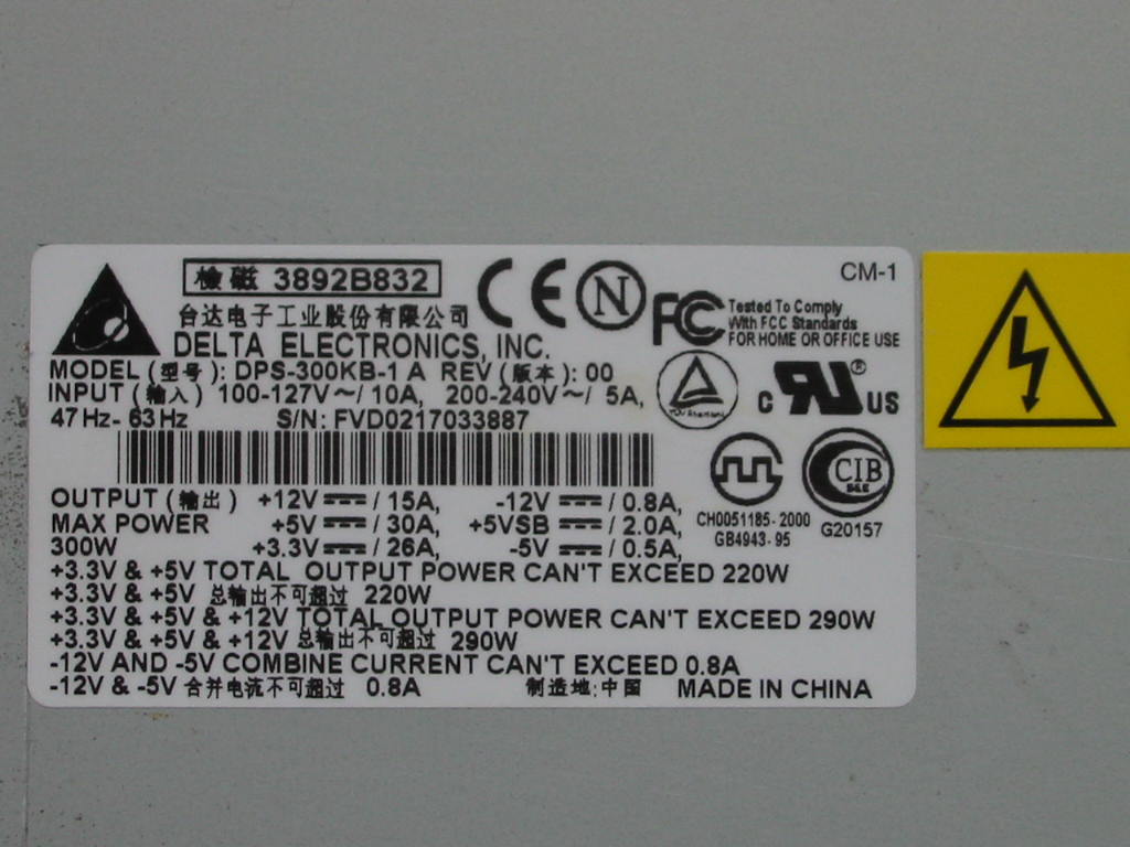
Wow, check that 3.3V/5V combined power rating: 220 Watts of awesomesauce! I challenge anyone to find me a retro PC that couldn’t be satisfied by that 3.3V/5V rating.
  Meanwhile, the 12V rail is rated for a modest 15 Amps (probably enough for early era Pentium 4 PCs.)
Anyways, let’s see what’s inside…
https://www.badcaps.net/forum/attach...1&d=1616221145
Heatisnks! And caps… and a 2nd PCB specifically for EMI/RFI filtering. I think I need to take it apart further to see more details.
First, the EMI/RFI board:
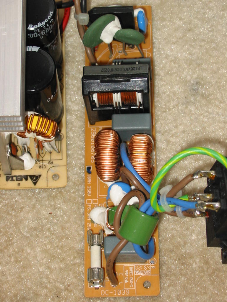
I think Delta is literally just trying to show-off here. We have 2x CM chokes, 2x SM chokes, 3x X2 caps, and 4x Y2 caps. Also notice the fuse is in a holder and it’s a ceramic-case fuse (how it should be.) And to top it off, there are 2x NTCs. Good job, Delta!
Now let’s look at the rest of the PSU.
https://www.badcaps.net/forum/attach...1&d=1616221145
https://www.badcaps.net/forum/attach...1&d=1616221145
When it comes to good heatsinks, these older PSUs from Delta (and HiPro) from the early 2000’s are pretty much as good as they get. No wonder the PSU weights a ton. And remember, this one is rated for only 300 Watts (though IMO, these units can probably peak up to 350 Watts without problems.) The transformer and output inductors are also quite big. And on the output side, we see quite a few 12.5 mm caps, which is always nice when it comes to recapping these PSUs (which, BTW, tend to suffer from bad caps a lot less frequently than the newer units.)
Anyways, here is the primary side:
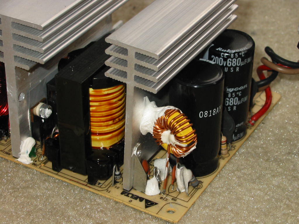
Input caps are 2x 200V, 680 uF Rubycon USR units - more than adequate for the power rating of this PSU. The little toroid inductor in the corner suggests this is a single-transistor forward design. Though not visible in the above picture, there are 2x 2SK2654 MOSFETs in TO-247 cases in parallel attached to that primary heatsink. Also, the main PS transformer does not use 35 mm wide core, but 39 mm - very nice!
Next, the secondary side…
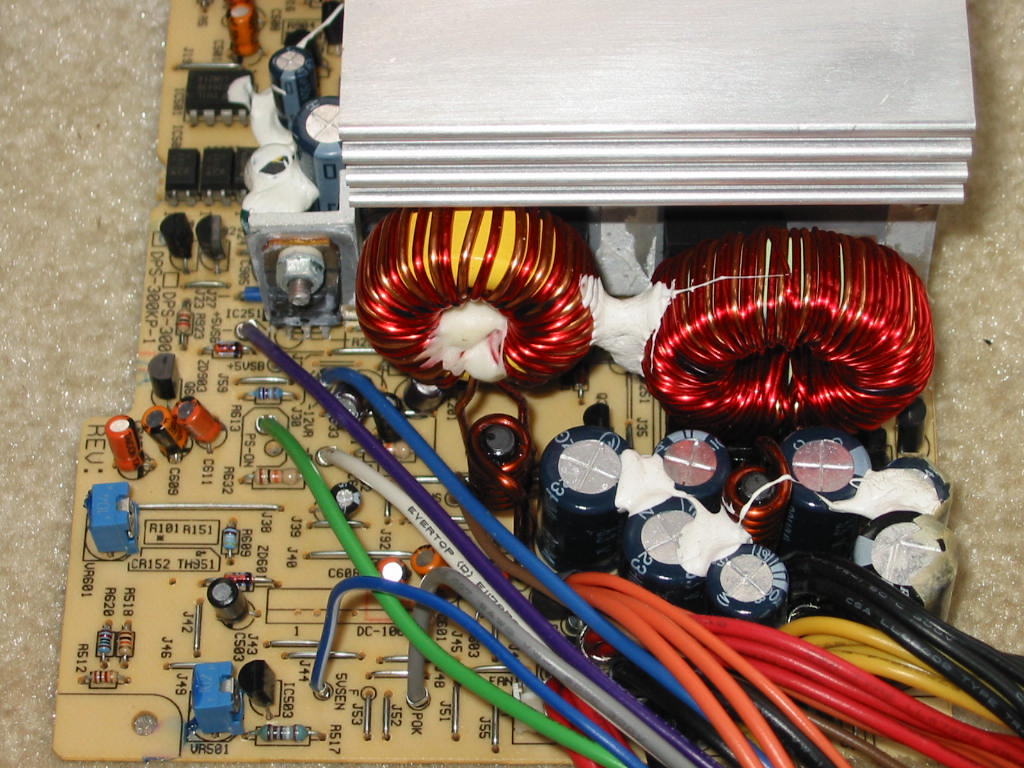
The output caps may look small at first, but that’s only because they are dwarfed by the output filter toroids. On that note, the main PS output toroid is a T130-52 (i.e. uses Micrometals -52 core material, as the light green color with one side painted blue shows.) The 3.3V rail toroid is only slightly smaller and uses -26 core material (T103-26, I think.) All in all, very good job there. Back to the output caps… again, no less than 4 of the output caps are 12.5 mm in diameter. Now the cap choices aren’t the best - mostly Ltec LZG. However, there is a single Rubycon YXG in there on the 12V rail (I guess Delta knows where it counts, as this PSU was installed in an early P4 MicronPC that drew power primarily from the 12V rail.) Another interesting thing to notice is the “5VSEN” (5V sense) line, in addition to the standard 3.3V sense line - Delta really wanted to make sure this PSU’s 5V and 3.3V rails performed top-notch.
What else is top notch? A yes, the soldering on the PCB:
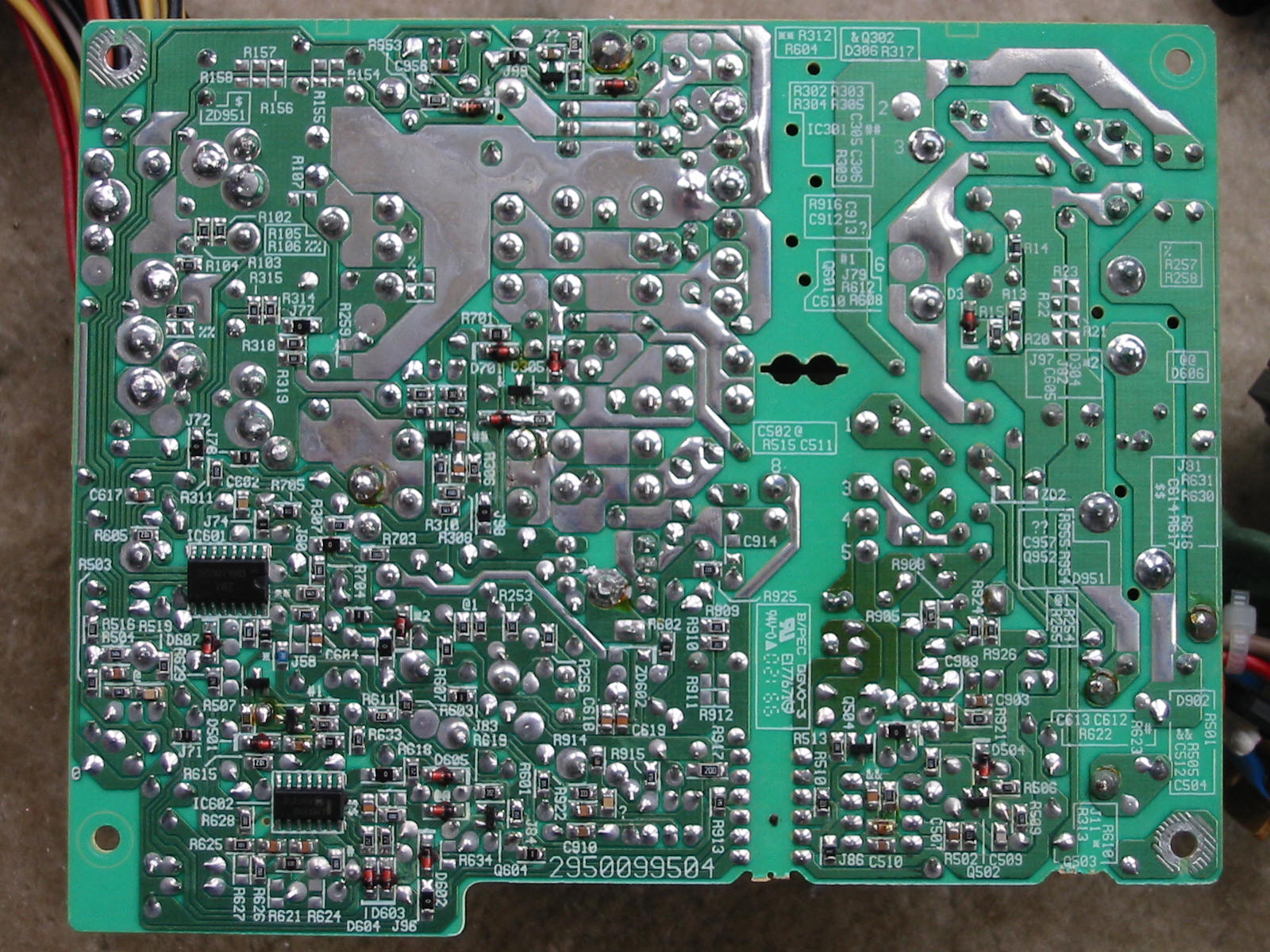
On the above shot, however, we can see a slight darkening in the lower-right side of the board. This corresponds to the 5VSB circuit - in particular, the area right around diode D901. Here is a better shot of the top-side of the 5VSB circuit area:
https://www.badcaps.net/forum/attach...1&d=1616221339
The 5VSB circuit is a 2-transistor design, so users of this PSU are advised to recap the 5VSB circuit (both the output and the “critical” cap on the primary side.) From what I can tell so far, the darkening around this diode is not related to the condition of the caps, as I’ve seen the same diode with the same darkening in other Delta PSUs. In particular, it seem the diode is dissipating the most heat when the 5VSB is unloaded, even though this is not the snubber circuit diode, but rather the primary-side auxiliary rectifier (which provides power to the UC384x PWM IC and primary-side 5VSB circuitry too.) I think it has more to do with the fact that Delta used a regular 1N4001 diode here instead of a fast-recovery rectifier. On that note, for those of you who may be thinking to just swap that diode, I advise caution to be used. While I was able to successfully swap this same diode on another newer Delta PSU (with same 2-transistor 5VSB) with a FR153 part, this DPS-300KB did not appreciate the change - the 5VSB lost regulation and started producing terrible screeching noise. So I returned back the original 1N4001 diode (but with a piece of long copper braid soldered to the Cathode lead for extra heatsinking) and the 5VSB operation returned back to normal. Thus, maybe there is a reason why Delta used a 1N4001 diode here. In any case, the thing runs miserably hot with unloaded or light-loaded 5VSB, so I suggest adding a heatsink to that diode, at least.
Last but not least, here’s a fan shot:
https://www.badcaps.net/forum/attach...1&d=1616221339
And that pretty much concludes all I have to say about this PSU, aside from the parts’ list below:
ICs:
UC3843b (PWM controller), DNA1002d (secondary-side supervisor), LM339 (secondary side protections or fan control?), and 7912 linear regulator (-12V rail)
Wiring:
* 600V, 18 AWG input wiring
* 300V, 18 AWG output wiring
* Output connectors: 20-pin ATX, 4-pin 12V CPU, 5x Molex drive, 1x floppy, 1x AUX
Primary Side:
* Input Filtering: three X2-class caps (2x 0.22 uF, 1x 0.1 uF), four Y2-class caps (either 2.2 nF or 3.3 nF), two CM chokes + two SM chokes
* Input protection: F10AH250V ceramic fuse, SCK 2R512 and SCK 056 NTC inrush current limiters, 2x MOVs across each cap for voltage surge protection
* 6 or 8 Amp (?) bridge rectifier (can’t read info due to being glued)
* 2x Rubycon USR, 200V, 680, 22x46 mm, 85°C caps
* P2NA60 MOSFET (TO-220) + MPS2222A BJT (TO-92) for 2-transistor 5VSB circuit
* 1x Ltec LZG, 50V, 47 uF, 6.3x11 mm “critical” cap
* 2x 2SK2654 MOSFETs (TO-247) in parallel for main PS
* ERL39 main PS transformer and ERL22 5VSB transformer
Secondary Side:
* 5VSB
*** 1x Ltec LZG, 6.3V, 2200 uF, 10x23 mm before PI coil (in a 12.5 mm spot)
*** 1x Taicon PW, 10V(?), 220(?) uF, 8x13 mm after PI coil (in a spot for 5 mm LS)
*** STPS10L40 (TO-220) rectifier
* 3.3V Rail
*** 2x Ltec LZG, 6.3V, 3300 uF, 12.5x20 mm with PI coil (5.5T, 5 mm core, 12 AWG wire) in between
*** 2x STPS3045cw (TO-247) Schottky rectifiers in parallel
*** 4x 180-Ohm SMD load resistors in parallel
* 5V Rail
*** 1x Ltec LZG, 6.3V, 3300 uF, 12.5x20 mm before PI coil (5.5T, 5 mm core, 12 AWG)
*** 1x Ltec LZG, 6.3V, 2200 uF, 10x23 mm after PI coil
*** 2x STPS3045cw (TO-247) Schottky rectifiers in parallel
*** 4x 390-Ohm SMD load resistors in parallel
* 12V Rail
*** 1x Ltec LTG, 16V, 1000(?) uF, 10x20 mm and 1x Rubycon YXG, 16V, 2200 uF, 12.5x25 mm (no PI coil)
*** 2x STPR1020ct (TO-220) Schottky rectifiers in parallel
*** 470-Ohm ½ Watt load resistor
* -12V Rail
*** 1x Ltec LZG, 16V (or 25V?), 470 uF, before 7912 linear regulator (no PI coil)
*** 1x Taicon VT, 25V, 47 uF, after 7912 linear regulator
*** 1.5 or 2 Amp diode as rectifier
* -5V Rail
*** 1x Taicon VT, 50V, 10 uF, after 7905 linear regulator (input being the “raw” -12V rail before the 7912 regulator.)
Another day, another Delta PSU… this time it’s an older one: DPS-300KB-1 A.
Unit has a classic clam-shell case (with a few rust spots, as it came from a dirty warehouse PC) and thick steel. For output connectors, we have the standard: 20-pin ATX, 4-pin 12V CPU, 5x Molex drive, and 1x floppy - all done with 18 AWG, 300V wires. There is also a 3.3V AUX connector for whatever reason. Just based on the weight of the PSU and good wires, one can tell it’s a well-built PSU.
Moving onto the label:
Wow, check that 3.3V/5V combined power rating: 220 Watts of awesomesauce!
 I challenge anyone to find me a retro PC that couldn’t be satisfied by that 3.3V/5V rating.
  Meanwhile, the 12V rail is rated for a modest 15 Amps (probably enough for early era Pentium 4 PCs.)
Anyways, let’s see what’s inside…
https://www.badcaps.net/forum/attach...1&d=1616221145
Heatisnks!
 And caps… and a 2nd PCB specifically for EMI/RFI filtering. I think I need to take it apart further to see more details.
 First, the EMI/RFI board:
I think Delta is literally just trying to show-off here.
 We have 2x CM chokes, 2x SM chokes, 3x X2 caps, and 4x Y2 caps. Also notice the fuse is in a holder and it’s a ceramic-case fuse (how it should be.) And to top it off, there are 2x NTCs. Good job, Delta!
Now let’s look at the rest of the PSU.
https://www.badcaps.net/forum/attach...1&d=1616221145
https://www.badcaps.net/forum/attach...1&d=1616221145
When it comes to good heatsinks, these older PSUs from Delta (and HiPro) from the early 2000’s are pretty much as good as they get. No wonder the PSU weights a ton. And remember, this one is rated for only 300 Watts (though IMO, these units can probably peak up to 350 Watts without problems.) The transformer and output inductors are also quite big. And on the output side, we see quite a few 12.5 mm caps, which is always nice when it comes to recapping these PSUs (which, BTW, tend to suffer from bad caps a lot less frequently than the newer units.)
Anyways, here is the primary side:
Input caps are 2x 200V, 680 uF Rubycon USR units - more than adequate for the power rating of this PSU. The little toroid inductor in the corner suggests this is a single-transistor forward design. Though not visible in the above picture, there are 2x 2SK2654 MOSFETs in TO-247 cases in parallel attached to that primary heatsink. Also, the main PS transformer does not use 35 mm wide core, but 39 mm - very nice!
Next, the secondary side…
The output caps may look small at first, but that’s only because they are dwarfed by the output filter toroids. On that note, the main PS output toroid is a T130-52 (i.e. uses Micrometals -52 core material, as the light green color with one side painted blue shows.) The 3.3V rail toroid is only slightly smaller and uses -26 core material (T103-26, I think.) All in all, very good job there. Back to the output caps… again, no less than 4 of the output caps are 12.5 mm in diameter. Now the cap choices aren’t the best - mostly Ltec LZG. However, there is a single Rubycon YXG in there on the 12V rail (I guess Delta knows where it counts, as this PSU was installed in an early P4 MicronPC that drew power primarily from the 12V rail.) Another interesting thing to notice is the “5VSEN” (5V sense) line, in addition to the standard 3.3V sense line - Delta really wanted to make sure this PSU’s 5V and 3.3V rails performed top-notch.
What else is top notch? A yes, the soldering on the PCB:
On the above shot, however, we can see a slight darkening in the lower-right side of the board. This corresponds to the 5VSB circuit - in particular, the area right around diode D901. Here is a better shot of the top-side of the 5VSB circuit area:
https://www.badcaps.net/forum/attach...1&d=1616221339
The 5VSB circuit is a 2-transistor design, so users of this PSU are advised to recap the 5VSB circuit (both the output and the “critical” cap on the primary side.) From what I can tell so far, the darkening around this diode is not related to the condition of the caps, as I’ve seen the same diode with the same darkening in other Delta PSUs. In particular, it seem the diode is dissipating the most heat when the 5VSB is unloaded, even though this is not the snubber circuit diode, but rather the primary-side auxiliary rectifier (which provides power to the UC384x PWM IC and primary-side 5VSB circuitry too.) I think it has more to do with the fact that Delta used a regular 1N4001 diode here instead of a fast-recovery rectifier. On that note, for those of you who may be thinking to just swap that diode, I advise caution to be used. While I was able to successfully swap this same diode on another newer Delta PSU (with same 2-transistor 5VSB) with a FR153 part, this DPS-300KB did not appreciate the change - the 5VSB lost regulation and started producing terrible screeching noise. So I returned back the original 1N4001 diode (but with a piece of long copper braid soldered to the Cathode lead for extra heatsinking) and the 5VSB operation returned back to normal. Thus, maybe there is a reason why Delta used a 1N4001 diode here. In any case, the thing runs miserably hot with unloaded or light-loaded 5VSB, so I suggest adding a heatsink to that diode, at least.
Last but not least, here’s a fan shot:
https://www.badcaps.net/forum/attach...1&d=1616221339
And that pretty much concludes all I have to say about this PSU, aside from the parts’ list below:
ICs:
UC3843b (PWM controller), DNA1002d (secondary-side supervisor), LM339 (secondary side protections or fan control?), and 7912 linear regulator (-12V rail)
Wiring:
* 600V, 18 AWG input wiring
* 300V, 18 AWG output wiring
* Output connectors: 20-pin ATX, 4-pin 12V CPU, 5x Molex drive, 1x floppy, 1x AUX
Primary Side:
* Input Filtering: three X2-class caps (2x 0.22 uF, 1x 0.1 uF), four Y2-class caps (either 2.2 nF or 3.3 nF), two CM chokes + two SM chokes
* Input protection: F10AH250V ceramic fuse, SCK 2R512 and SCK 056 NTC inrush current limiters, 2x MOVs across each cap for voltage surge protection
* 6 or 8 Amp (?) bridge rectifier (can’t read info due to being glued)
* 2x Rubycon USR, 200V, 680, 22x46 mm, 85°C caps
* P2NA60 MOSFET (TO-220) + MPS2222A BJT (TO-92) for 2-transistor 5VSB circuit
* 1x Ltec LZG, 50V, 47 uF, 6.3x11 mm “critical” cap
* 2x 2SK2654 MOSFETs (TO-247) in parallel for main PS
* ERL39 main PS transformer and ERL22 5VSB transformer
Secondary Side:
* 5VSB
*** 1x Ltec LZG, 6.3V, 2200 uF, 10x23 mm before PI coil (in a 12.5 mm spot)
*** 1x Taicon PW, 10V(?), 220(?) uF, 8x13 mm after PI coil (in a spot for 5 mm LS)
*** STPS10L40 (TO-220) rectifier
* 3.3V Rail
*** 2x Ltec LZG, 6.3V, 3300 uF, 12.5x20 mm with PI coil (5.5T, 5 mm core, 12 AWG wire) in between
*** 2x STPS3045cw (TO-247) Schottky rectifiers in parallel
*** 4x 180-Ohm SMD load resistors in parallel
* 5V Rail
*** 1x Ltec LZG, 6.3V, 3300 uF, 12.5x20 mm before PI coil (5.5T, 5 mm core, 12 AWG)
*** 1x Ltec LZG, 6.3V, 2200 uF, 10x23 mm after PI coil
*** 2x STPS3045cw (TO-247) Schottky rectifiers in parallel
*** 4x 390-Ohm SMD load resistors in parallel
* 12V Rail
*** 1x Ltec LTG, 16V, 1000(?) uF, 10x20 mm and 1x Rubycon YXG, 16V, 2200 uF, 12.5x25 mm (no PI coil)
*** 2x STPR1020ct (TO-220) Schottky rectifiers in parallel
*** 470-Ohm ½ Watt load resistor
* -12V Rail
*** 1x Ltec LZG, 16V (or 25V?), 470 uF, before 7912 linear regulator (no PI coil)
*** 1x Taicon VT, 25V, 47 uF, after 7912 linear regulator
*** 1.5 or 2 Amp diode as rectifier
* -5V Rail
*** 1x Taicon VT, 50V, 10 uF, after 7905 linear regulator (input being the “raw” -12V rail before the 7912 regulator.)

 So maybe not that overkill, after all. There is also a 13007 NPN BJT on the primary (Q2) and an 8-pin (PWM?) IC that I couldn't read what part number it had. So I'm not sure what kind of design this is, but it sure isn't 2-transistor. Main transformer has an EI-28 mm core, which is more than large enough. On the output-side of things, there is a FCH20A15 (20 Amp, 150V Schottky) in TO-220FP isolated case. And finally, the filtering caps are 1x United Chemicon KY, 35V, 1000 uF, 12.5x20 mm and 1x United Chemicon KY(?), 35V(?), 330(?) uF, 10x16 mm.
 The two bulged ones are on the 3.3V rail, and I bet that's why this PSU was “abandoned”.
  Should be an easy fix. The more of these OEM PSUs I recap, the more I like them. This one should be pretty easy with the caps, as both the 3.3V and 5V rails use 2x 2200 uF caps each. Meanwhile, the 5VSB and 12V rails have 1x 16V, 1500 uF each. On that note, I would have liked to see a slightly bigger capacity cap on the 12V rail. Perhaps this is the reason for the 19 Amp rating. Otherwise everything else checks out to allow for a lot more. In fact, the “12V rectifier” consists of 2x SPTS20H100 Schottky diodes, where one of them is solely used for the forward rectification while the other is used solely for the free-wheeling. Therefore, this is not just a regular “parallel” setup, and I honestly expect the 12V rail to be capable of much more than 20 Amps (perhaps 25-30A with bigger output filter cap.) The 12V rail is coupled to the 5V rail too, so regulation and 12V-heavy cross-loading shouldn't be a problem… though I will test that eventually, after I recap the PSU.
 ), 2x MOVs across each cap
 Last was V650
  Half of the computer problems is caused by bad contacts
Comment