
Hello everyone,
I've got a laptop in after a screen replacement where the lid-sensor is non-responsive; I have been assured that all magnets were transferred over.
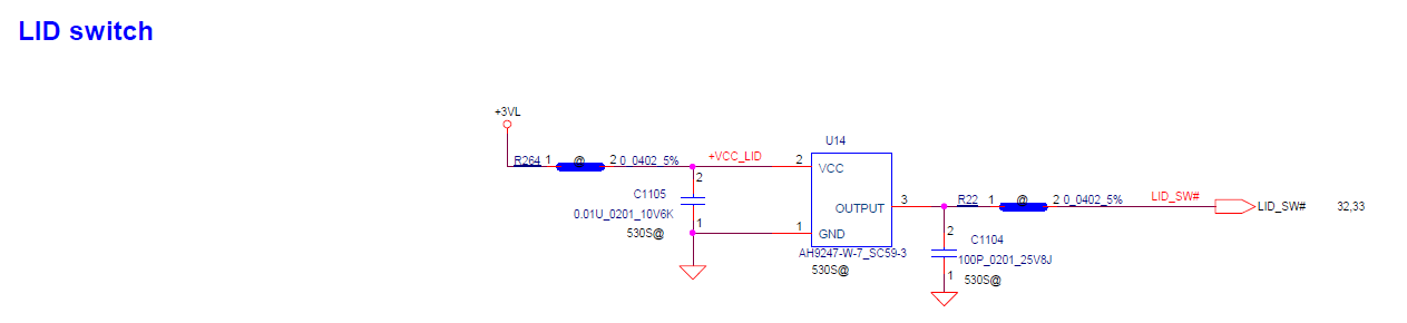
I can't physically see any hall-sensors on the board, nor will a magnet anywhere around the board do anything.
Looking at the Schematics I can find the Hall Sensor and its component designation (U14), I also note that J3 (the USB sub-board connector) has pins 26&27 as LID Signals #1 and #2 and pin 28 is +3VL VCC.

Because I couldn't visually locate the component, I was going to attempt to short the LID pin to ground and see if it triggered sleep, however, when I look at the schematics for the sub-board itself the pin orientation has been reversed and pins 1,2&3 are crossed out.

Am I reading these schematics right?
If anyone has any insight I would much appreciate it!
I've got a laptop in after a screen replacement where the lid-sensor is non-responsive; I have been assured that all magnets were transferred over.
I can't physically see any hall-sensors on the board, nor will a magnet anywhere around the board do anything.
Looking at the Schematics I can find the Hall Sensor and its component designation (U14), I also note that J3 (the USB sub-board connector) has pins 26&27 as LID Signals #1 and #2 and pin 28 is +3VL VCC.
Because I couldn't visually locate the component, I was going to attempt to short the LID pin to ground and see if it triggered sleep, however, when I look at the schematics for the sub-board itself the pin orientation has been reversed and pins 1,2&3 are crossed out.
Am I reading these schematics right?
If anyone has any insight I would much appreciate it!

Comment