![]() |
|
|
Thread Tools | Display Modes |
![]() |
#1 |
Ontario Member
Join Date: May 2009
City & State: Brockville, Ontario
My Country: Canada
I'm a: Knowledge Seeker
Posts: 40
|
![]() I was given a dead samsung 920N LCD to play with and put it aside because the faulty electronics did not appear to be due to bad caps.
There ware no mounded caps. All the caps passed the scope, oscillator, resistor: ESR test. 
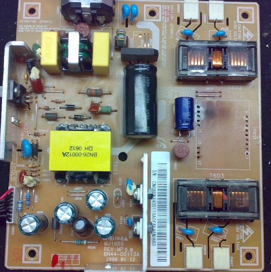
There were 3 broken foils on the MJ19BS inverter/power board to the MJ17BS hybrid assembly pins 15,16 & 17 which were easy to repair. Still, no backlighting. I isolated the fault to the MJ17BS hybrid pulling down the 13v (hybrid pin 12) by removing the hybrid. It was starting to look like an expensive repair so I set the LCD aside. Then I came across a Russian site that appeared to show a repair to the E6N03, dual FET chip on the MJ17BS hybrid. Which is likely to be at fault in my case as the FETS sink most of the current. 
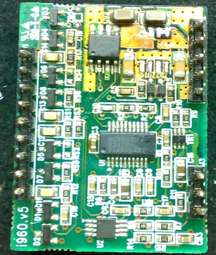
The E6N03 is the missing 8 pin, surface mounted device in the upper right on the photo of the MJ17BS hybrid. This fix is a bit outside of my confort zone. Has anyone tried to repair a surface mounted component on a hybrid? What should I be careful of? Where can the E6N03 be sourced when I am only buying one or two (in case I screw-up the soldering). big CHEERS to the folks at BadCaps.
__________________
Be yourself, everyone else is taken. |
![]() |
![]() |
![]() |
#2 |
Ontario Member
Join Date: May 2009
City & State: Brockville, Ontario
My Country: Canada
I'm a: Knowledge Seeker
Posts: 40
|
![]() The E6N03 part location in the previous post was not correct.
I'll try again. The E6N03 is a dual FET. Data Sheet attached pdf document: http://www.badcaps.net/forum/attachm...id=12870&stc=1 The missing 8 pin surface mounted device in the photo is labeled PF7SR, FDS on the hybrid that I am looking at. I cannot locate any info. on PF7SR but I may also have misread the device label. These tiny parts are not so easy to see; anymore. Thank you in advance. Cheers |
![]() |
![]() |
![]() |
#3 |
Ontario Member
Join Date: May 2009
City & State: Brockville, Ontario
My Country: Canada
I'm a: Knowledge Seeker
Posts: 40
|
![]() I am still trying to piece this hybrid fix together.
The 8-pin device that was removed from the hybrid photo below appeared to be: PF7SR, FDS. Another Russian blog post about the samsung 913N suggested that the "PF7SR FDS" is an FDS4935A. pdf data sheet attached: http://www.badcaps.net/forum/attachm...id=12871&stc=1 What is the best method to remove these surface mounted devices from the hybrid? Am I way "out there" on this one? Cheers |
![]() |
![]() |
![]() |
#4 | |
Badcaps Veteran
Join Date: Feb 2009
City & State: Phoenix, AZ
My Country: USA
Line Voltage: 120VAC 60Hz
I'm a: Hobbyist
Posts: 7,012
|
![]() Quote:
PlainBill
__________________
For a number of reasons, both health and personal, I will no longer be active on this board. Any PMs asking for assistance will be ignored. Never be afraid to try something new. Remember, amateurs built the ark. Professionals built the Titanic. |
|
![]() |
![]() |
![]() |
#5 |
Ontario Member
Join Date: May 2009
City & State: Brockville, Ontario
My Country: Canada
I'm a: Knowledge Seeker
Posts: 40
|
![]() That is too cool, PlainBill.
The idea being; change the surface mount solder in to something less sticky. I am going to get some just to try it out. THX. The method I resorted to involved an exacto-knife and a fine tipped iron. The IC leads were severed from the main part of the chip as close to the IC as possible using the exacto-knife and downward pressure. Care had to be taken not to cut foil traces on the hybrid substrate that were in the path of the knife blade. When all the IC leads were severed, the IC was removed and discarded. The remaining part of the IC leads that were soldered to the solder pads on the hybrid substrate were removed using a fine tip iron and copper braid. Worked well this time but the 'Chip Quik' is likely to be the prefered method for the future. rgs, Kevin |
![]() |
![]() |
![]() |
#6 |
Badcaps Veteran
Join Date: Jan 2007
City & State: New Jersey, USA
Posts: 2,283
|
![]() Before I discovered Chip Quik and was replacing BA chips (DVD driver ICs) on PS2s I used a cutting wheel on a Dremel and buzzed the leads off where they met the package.
Then I flicked the leads off with an iron same theory as the Exacto just quicker. I used Chipquik my first time on a Panasonic 27" TVs shot 40 pin Chroma / Micro IC. Worked great just make sure you shoot the flux from the syringe that comes with the kit on there before using the alloy because it's expensive and won't flow properly without it. Also shoot the flux on the new ICs leads before soldering the IC since you will be putting the solder on the iron tip first. Which will burn off all the flux that's the smoke you see when soldering. Applying solder to the tip first is a no no with through hole but with SMT is a necessity since the leads are so small.
__________________
Elements of the past and the future combining to make something not quite as good as either. Last edited by Krankshaft; 12-18-2009 at 08:02 AM.. |
![]() |
![]() |
![]() |
#7 |
Ontario Member
Join Date: May 2009
City & State: Brockville, Ontario
My Country: Canada
I'm a: Knowledge Seeker
Posts: 40
|
![]() Repaired the hybrid (see the attached png.s)
...improved on the second try. The component moves around as it is soldered. A dot of crazy glue helps hold the part in place. Works good, now. Thanks to all that contributed. |
![]() |
![]() |
![]() |
#8 |
Badcaps Veteran
Join Date: Mar 2008
Posts: 2,296
|
![]() Fixed yet?
Cheers, Wizard |
![]() |
![]() |
![]() |
#9 |
Ontario Member
Join Date: May 2009
City & State: Brockville, Ontario
My Country: Canada
I'm a: Knowledge Seeker
Posts: 40
|
![]() Worked for a bit then went for a s..t.
rgs, Kevin |
![]() |
![]() |
![]() |
#10 |
New Member
Join Date: Mar 2010
Posts: 1
|
![]() Hello! I have a big problem and I hope that you can help me.For this I need a monitor EDID in txt file. How to download this edid and what program is downloaded on this site http://www.avforums.com/forums/lcd-l...-signal-3.html. I apologize for my English and I hope that you can help me. Thanks!
|
![]() |
![]() |
![]() |
#11 |
New Member
Join Date: Jul 2010
Posts: 1
|
![]() |
![]() |
![]() |
![]() |
#12 |
New Member
Join Date: Nov 2010
Posts: 1
|
![]() datasheet BN44-00113a (no very gut)
I want datasheet MJ17BS (foto) Last edited by vsimanin; 11-29-2010 at 01:06 PM.. |
![]() |
![]() |
![]() |
#13 |
New Member
Join Date: Dec 2011
Posts: 3
|
![]() Hello to everyone.
I have 3 samsung 920n with no image and flashing led. I changed all the capacitors in one of them and the led is now ok on/off . but there is no image and there is a sound like tsssss when i put the powered wire in. the ps board is ip-35135a. any ideas? i am a nubie in electronics. thank you. |
![]() |
![]() |
![]() |
#14 | |
Member
Join Date: Mar 2010
City & State: st.louis mo
Posts: 1,300
|
![]() Quote:
Check the MOSFETS for shorted condition, replace as required. Check and replace inverter fuse.
__________________
Whatever I do, I consider it a success, if in the end I am breathing, seeing, feeling and hearing! ![]() |
|
![]() |
![]() |
![]() |
#15 |
New Member
Join Date: Dec 2011
Posts: 3
|
![]() Thank you for your reply, the fuse its ok.The mofset needs to be desoldered to test right?
I'll do it and tell you the results. I also have a another monitor that display only for one second. I checked the capacitors but they seem to be fine. any ideas? |
![]() |
![]() |
![]() |
Thread Tools | |
Display Modes | |
|
|