![]() |
|
|
Thread Tools | Display Modes |
![]() |
#1 |
Senior Member
Join Date: Sep 2019
City & State: Southampton
My Country: United Kingdom
I'm a: Knowledge Seeker
Posts: 109
|
![]() Hi,
I have the above TV which will not turn on. I understand the flash code is pointing to a faulty inverter board: 
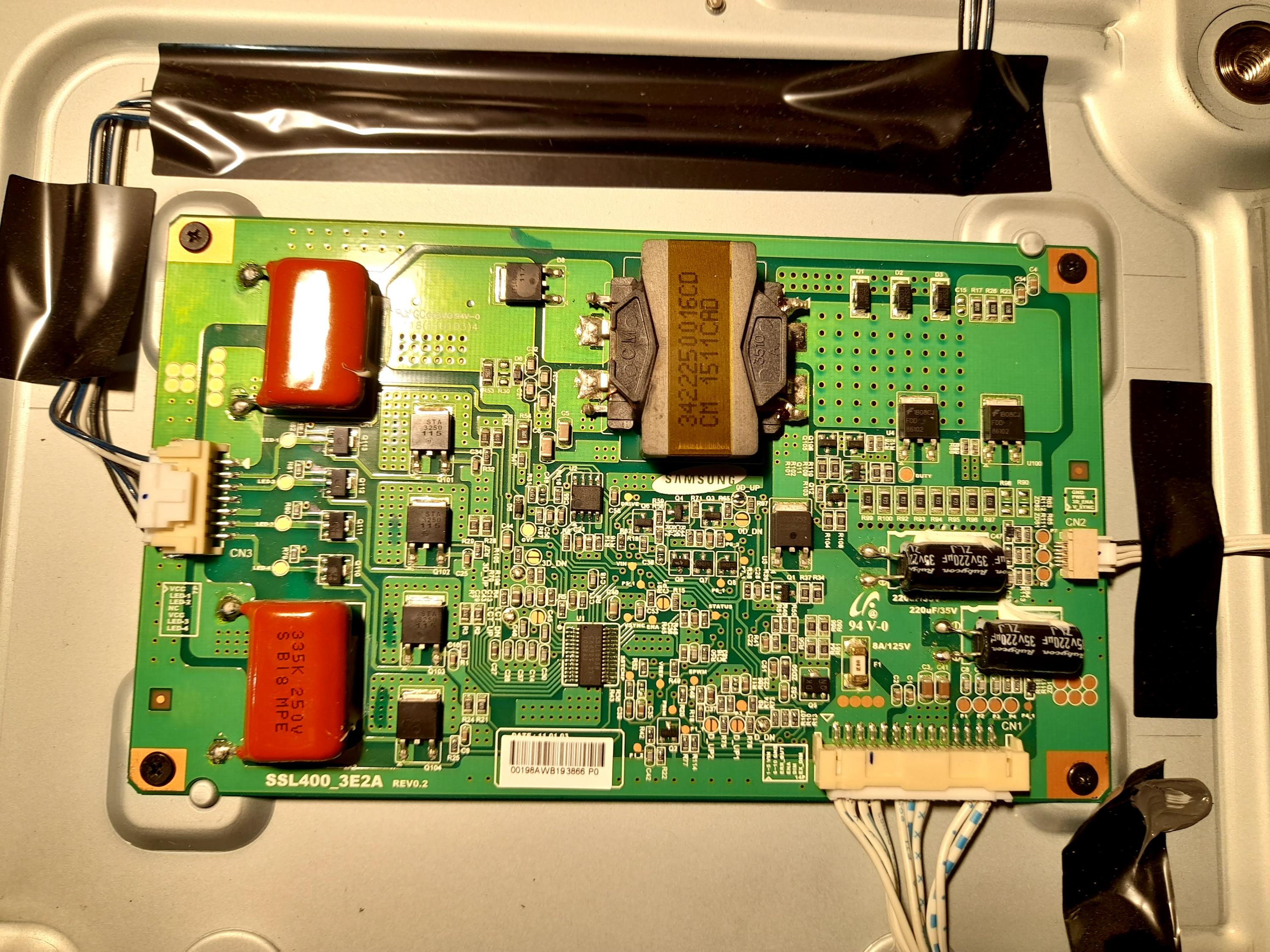
The main connector on the bottom connector has the following readings when the LED is blinking Red/Green (from left to right) 1. 24v 2. 24v 3. 24v 4. 24v 5. N/C 6. GND 7. GND 8. GND 9. N/C 10. N/C 11. N/C 12. 0.013v 13. 3.3v 14. N/C any ideas where to start? Thanks in advance. |
![]() |
![]() |
![]() |
#2 |
Badcaps Veteran
Join Date: Aug 2015
City & State: Cardiff
My Country: Wales
Line Voltage: 230V AC, 50Hz
I'm a: Hobbyist Tech
Posts: 5,920
|
![]() Do you have 24V on each side of the fuse F1?
__________________
Willing to help but I'm no expert. |
![]() |
![]() |
![]() |
#3 |
Badcaps Veteran
Join Date: Feb 2013
City & State: SA
My Country: Germany
I'm a: Professional Tech
Posts: 2,224
|
![]() your reading of the voltage on CN1 look not correct with pins NO
you have pins 1-5 24V and from 6-10 GND , pin 11 are error out you wrote N/C second read the voltage on CN3 between VCC Pin1(red probe ) and led 1 & 2, same to the next VCC pin5 and led 3 & 4 |
![]() |
![]() |
![]() |
#4 |
Senior Member
Join Date: Sep 2019
City & State: Southampton
My Country: United Kingdom
I'm a: Knowledge Seeker
Posts: 109
|
![]() Fuse F1 is good.
I have rechecked what I listed for CN1 and i'm correct with the population of pins in the connector. With CN3, the connector to the LED strings I think I measured as you requested. As you look at the connector, with arrow on the right I used that as my + red reference That is pin1. 1. VCC (+reference) 2. LED1 10.50V 3. LED2 10.56V 4. NC 5. VCC 0.0V 6. LED3 10.58V 7. LED4 10.55 ..and the 2 electrolytics are fine ESR/capacitance wise Last edited by Nevillet; 01-12-2021 at 04:15 PM.. Reason: more info |
![]() |
![]() |
![]() |
#5 | |
Badcaps Veteran
Join Date: Feb 2013
City & State: SA
My Country: Germany
I'm a: Professional Tech
Posts: 2,224
|
![]() Quote:
i forget to mention this test of CN3 you need to put the probe on the test point then plug the set in wall socket to remark the high and low reading at each pins. i dont think the issue at inverter.. you have CN2 which i think its connected to the T-CON correct ? |
|
![]() |
![]() |
![]() |
#6 |
Badcaps Veteran
Join Date: Feb 2010
City & State: S.F. Bay area
My Country: USA
Line Voltage: 120V 60Hz
I'm a: Knowledge Seeker
Posts: 39,051
|
![]() 12. 0.013v
Pin 12 is ENA (BL-ON pin), <1V = Backlights OFF, > 2 ~ 2.5V = Backlights on TV is off, Put black probe on the chassis, red probe on PIN 12 (ENA = BL-ON), turn on the TV while watching the meter to see if it jumps up over 2VDC or not.
__________________
Never stop learning Basic LCD TV and Monitor troubleshooting guides. http://www.badcaps.net/forum/showthr...956#post305956 Voltage Regulator (LDO) testing: http://www.badcaps.net/forum/showthr...999#post300999 Inverter testing using old CFL: http://www.badcaps.net/forum/showthr...er+testing+cfl Tear down pictures : Hit the ">" Show Albums and stories" on the left side http://s807.photobucket.com/user/budm/library/ TV Factory reset codes listing: http://www.badcaps.net/forum/showthread.php?t=24809 |
![]() |
![]() |
![]() |
#7 |
Senior Member
Join Date: Sep 2019
City & State: Southampton
My Country: United Kingdom
I'm a: Knowledge Seeker
Posts: 109
|
![]() If I measure CN3 pin 5 VCC to pin 6 and pin 7 I read the same 10.5v
This measurement is taken when the front LED is blinking red/green. If i disconnect the TV from the wall supply - then reconnect, the front LED goes solid red. If I measure CN3 in this state these are the readings: 1. VCC 2. LED1 (pin1 to pin2 = 1.75v) 3. LED2 (pin1 to pin3 = 1.76v) 4. NC 5. VCC 6. LED3 (pin5 to pin6 = 1.8v) 7. LED4 (pin5 to pin7 = 1.68v) CN2 Connects to the T-Con board. Measuring CN1 pin12 with reference to ground: In standby 0.413v In 'on' 0.013v (using a Fluke 187 it does not appear to jump over 2v) |
![]() |
![]() |
![]() |
#8 |
Badcaps Veteran
Join Date: Aug 2015
City & State: Cardiff
My Country: Wales
Line Voltage: 230V AC, 50Hz
I'm a: Hobbyist Tech
Posts: 5,920
|
![]() .
Last edited by dick_barton; 01-13-2021 at 07:46 AM.. |
![]() |
![]() |
![]() |
#9 |
Senior Member
Join Date: Sep 2019
City & State: Southampton
My Country: United Kingdom
I'm a: Knowledge Seeker
Posts: 109
|
![]() Hi Dick,
I can't read any text in your 1:43 #8 posting. |
![]() |
![]() |
![]() |
#10 |
Badcaps Veteran
Join Date: Aug 2015
City & State: Cardiff
My Country: Wales
Line Voltage: 230V AC, 50Hz
I'm a: Hobbyist Tech
Posts: 5,920
|
![]() Sorry. I initially replied with a comment but then noticed after posting that I had made a mistake. Once posted there is no way to delete the posting other than to blank it.
|
![]() |
![]() |
![]() |
#11 |
Senior Member
Join Date: Sep 2019
City & State: Southampton
My Country: United Kingdom
I'm a: Knowledge Seeker
Posts: 109
|
![]() Understood. Many thanks.
|
![]() |
![]() |
![]() |
#12 | |
Badcaps Veteran
Join Date: Feb 2013
City & State: SA
My Country: Germany
I'm a: Professional Tech
Posts: 2,224
|
![]() Quote:
|
|
![]() |
![]() |
![]() |
#13 |
Senior Member
Join Date: Sep 2019
City & State: Southampton
My Country: United Kingdom
I'm a: Knowledge Seeker
Posts: 109
|
![]() Hi,
The TV is face down on the bench and to disconnect from the AC outlet I have been pulling out the Live+Neutral connection from the power board. I have not been using the remote control, rather the push buttons on the lower edge of the TV bezel to take it out of standby. Is this not achieving the same results? |
![]() |
![]() |
![]() |
#14 |
Badcaps Veteran
Join Date: Feb 2013
City & State: SA
My Country: Germany
I'm a: Professional Tech
Posts: 2,224
|
![]() yes of course its same.. so mean all the voltage you posted at your POST#7 after you press power on the side panel of the tv...?
|
![]() |
![]() |
![]() |
#15 |
Senior Member
Join Date: Sep 2019
City & State: Southampton
My Country: United Kingdom
I'm a: Knowledge Seeker
Posts: 109
|
![]() I remeasured everything. It looks like there is a problem with the Pin 6 measurement. The connector to the LED strings was connected during these readings.
Standby Pin-1 VCC Pin-2 V between P1 & P2 0.884v Pin-3 V between P1 & P3 0.836v Pin-4 No Connection Pin-5 V between P7 & P5 0.543v Pin-6 V between P7 & P6 0.010v Pin-7 VCC On Pin-1 VCC Pin-2 V between P1 & P2 10.55v Pin-3 V between P1 & P3 10.24v Pin-4 No Connection Pin-5 V between P7 & P5 10.02v Pin-6 V between P7 & P6 0.020v Pin-7 VCC |
![]() |
![]() |
![]() |
#16 | |
Badcaps Veteran
Join Date: Feb 2013
City & State: SA
My Country: Germany
I'm a: Professional Tech
Posts: 2,224
|
![]() Quote:
the one i remark it with red color ... you mean between pin7 LED 4 and Pin 5 VCC correct? |
|
![]() |
![]() |
![]() |
#17 |
Badcaps Veteran
Join Date: Feb 2013
City & State: SA
My Country: Germany
I'm a: Professional Tech
Posts: 2,224
|
![]() as end.. CN3, seem the first group blue pin1 to white & black okay
the second group blue pin 5 to white okay.. and to black pin 7 had open LED |
![]() |
![]() |
![]() |
#18 |
Senior Member
Join Date: Sep 2019
City & State: Southampton
My Country: United Kingdom
I'm a: Knowledge Seeker
Posts: 109
|
![]() No there is no typo. The voltage on P6-P7 is low in both states.
|
![]() |
![]() |
![]() |
#19 |
Senior Member
Join Date: Sep 2019
City & State: Southampton
My Country: United Kingdom
I'm a: Knowledge Seeker
Posts: 109
|
![]() Sorry, Sorry.
Crazy mistake on my part. Pin7 is not VCC for LED 3 & 4. Pin5 is VCC for pins 6 & 7 I will recheck all tomorrow when I'm not so tired. Sincere thanks for your help |
![]() |
![]() |
![]() |
#20 |
Badcaps Veteran
Join Date: Feb 2010
City & State: S.F. Bay area
My Country: USA
Line Voltage: 120V 60Hz
I'm a: Knowledge Seeker
Posts: 39,051
|
![]() https://www.badcaps.net/forum/attach...0&d=1610474573
What DC Voltage do you get on U3 Middle pin (big tab) with ref. to the negative leg one of 220uf 35V cap (the two caps are connected in parallel so you can use any one of the two caps)? |
![]() |
![]() |
![]() |
Thread Tools | |
Display Modes | |
|
|