Re: HP Power Supply help
That is TO-3 case is 5V Regulator IC U12.
See attached of PDF for the SCH of the board as shown in post 1.
Originally posted by Drack
View Post
See attached of PDF for the SCH of the board as shown in post 1.
Attached Files
 <----Computer says I need more beer.
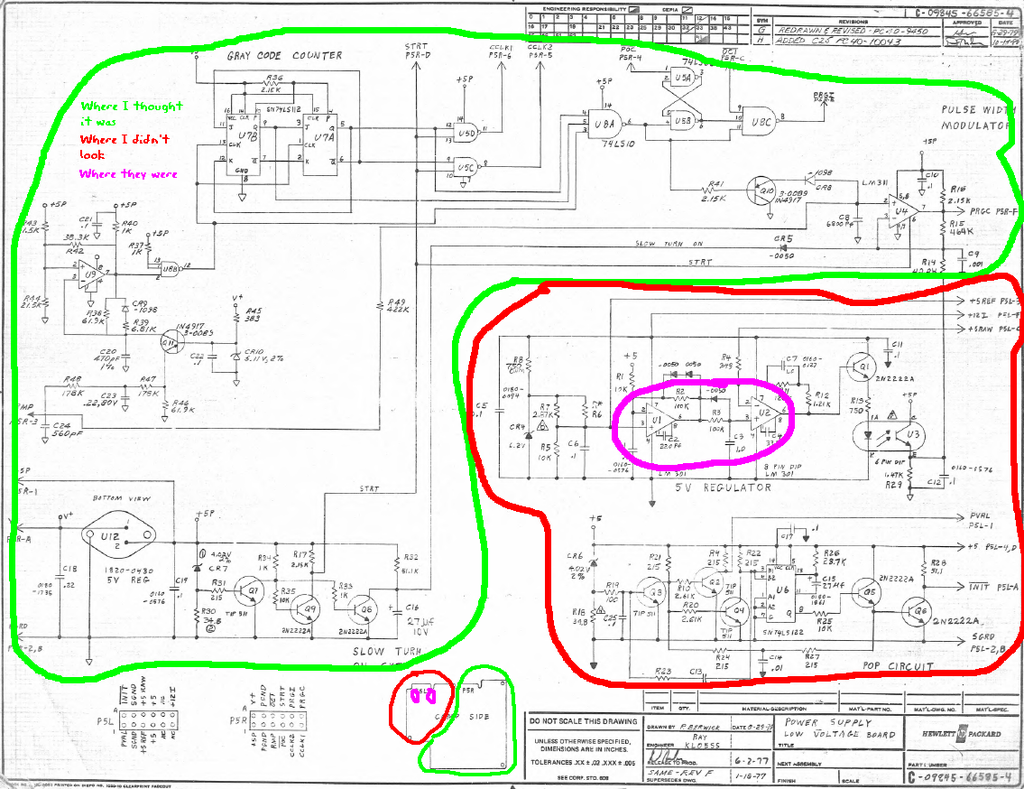
Comment