Hi All,
I'm looking at a Finlux (Vestel) TV which is stuck in standby. On inspection, the power board had 3 bulging caps (C851, 970,969) which were replaced with Rubycon ZL series. (they are a strange angles at the moment to ensure I have a decent lead length if they are removed) The standby problem did not resolve it self.
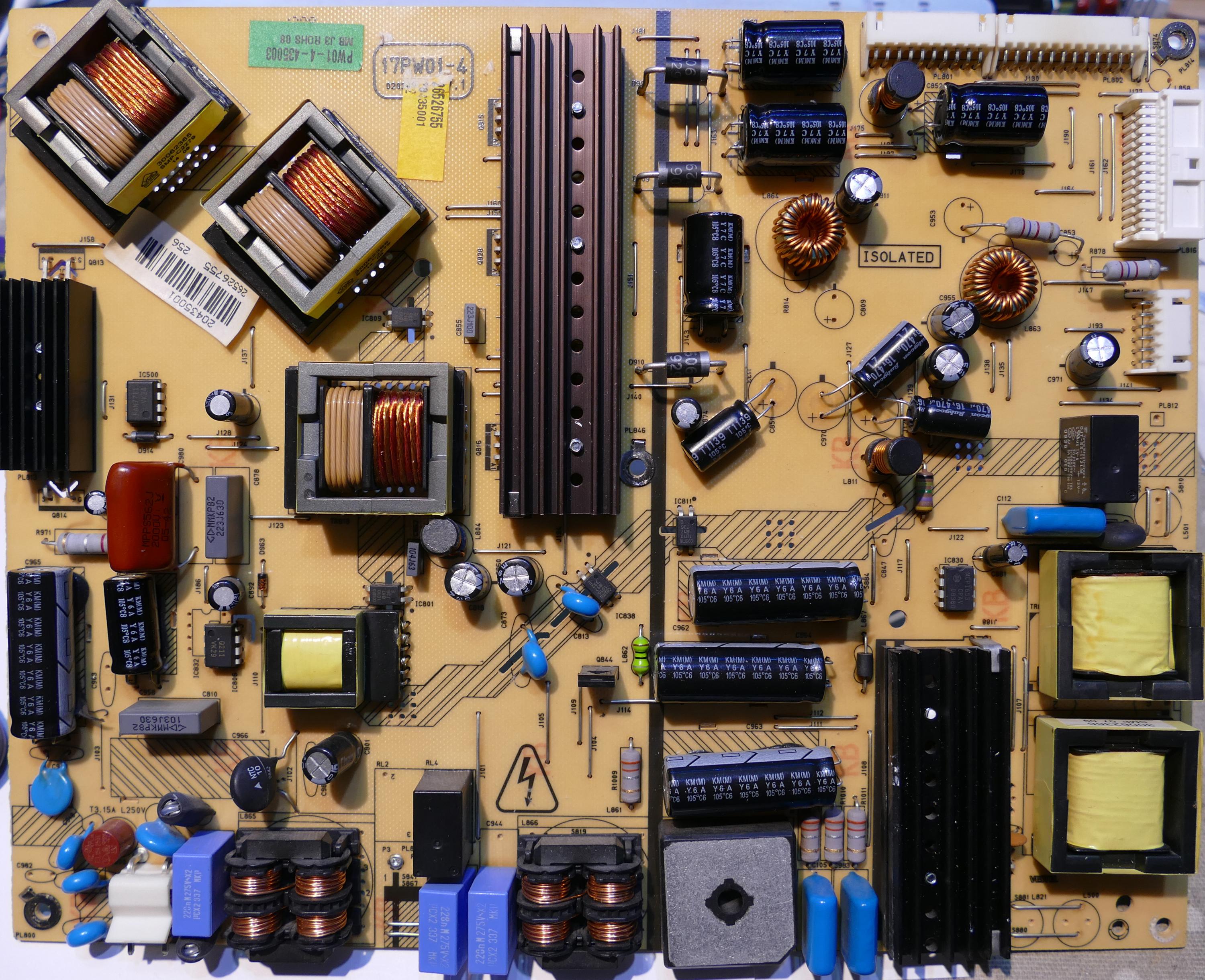
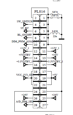
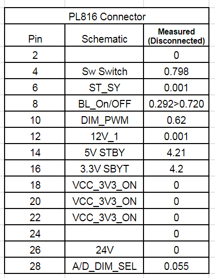
Off the TV i've measured the voltages of the PL816 connector that goes to the main logic board. The readings are below:
The original capacitors are Samxon brand. I've measured the ESR and capacitance and all apear within 'normal limits'. (I had to desolder them as some of them were in parallel and I was getting skewed results)
Similarly. I desoldered the big power diodes which were all fine.
As a general question, on a normally functioning PS board what kind of voltage variance would you expect on the +5V & +3.3V lines?
Any pointers would be most welcome.
I'm looking at a Finlux (Vestel) TV which is stuck in standby. On inspection, the power board had 3 bulging caps (C851, 970,969) which were replaced with Rubycon ZL series. (they are a strange angles at the moment to ensure I have a decent lead length if they are removed) The standby problem did not resolve it self.
Off the TV i've measured the voltages of the PL816 connector that goes to the main logic board. The readings are below:
The original capacitors are Samxon brand. I've measured the ESR and capacitance and all apear within 'normal limits'. (I had to desolder them as some of them were in parallel and I was getting skewed results)
Similarly. I desoldered the big power diodes which were all fine.
As a general question, on a normally functioning PS board what kind of voltage variance would you expect on the +5V & +3.3V lines?
Any pointers would be most welcome.
Attached Files
Comment