(TL;DR skip the first paragraph)
I encountered my first dead motor run capacitor at a customer this week.
For some fields I guess it is a very common occurrence but the usual way for industrial machines here is to use 3-phase motors.
(Unless a servo motor makes more sense that is).
But for some reason this 3-phase machine uses a 1-phase motor for its liquid coolant pump.
The pump would run but sometimes trip the 10A breaker.
I monitored it starting and stopping for over an hour until it finally stopped in a specific spot between its windings:
Then it could not start rotating again, so instead of drawing below 5A it suddenly took 15A
And that led me to the motor run capacitor, its print reads 25uF 400v but it measured 0.4nF, no wonder the motor was unhappy
The capacitor was mounted in a little sheet metal box opposite the input terminal connections of the motor.
Now the original capacitor measures 40mm wide by 74mm long and is manufactured by 미래콘덴서 in South Korea.
This does not seem to be a common size, the major distributors like Mouser and Elfa lists caps that are 45x74mm or 40x92mm.
At my job I found a 45x70mm capacitor that I did manage to squeeze in with some persuasion into the metal box, however it is only rated at 370v.
And here comes my question: when I measured the AC voltage across the capacitor with the motor running it was 363v.
The machine is american and has a 400v step-down transformer, the motor seems to be fed by something we never see in Europe: split phase.
That is from one hot or the other to ground I measure 133v.
But from both hots I measure 230v, this checks out with: √3 x 133v = 230v.
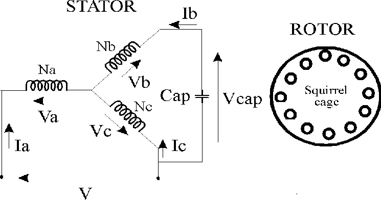
What I do not understand then is how can the voltage be 363v on the capacitor, should it not also see 230v?
I gratuitously stole this diagram of how I guess the motor is wired, but the 363v reading at Vcap then makes no sense to me.
Is the meter just being fooled by the phase-shift imposed by the capacitor?
I encountered my first dead motor run capacitor at a customer this week.
For some fields I guess it is a very common occurrence but the usual way for industrial machines here is to use 3-phase motors.
(Unless a servo motor makes more sense that is).
But for some reason this 3-phase machine uses a 1-phase motor for its liquid coolant pump.
The pump would run but sometimes trip the 10A breaker.
I monitored it starting and stopping for over an hour until it finally stopped in a specific spot between its windings:
Then it could not start rotating again, so instead of drawing below 5A it suddenly took 15A
And that led me to the motor run capacitor, its print reads 25uF 400v but it measured 0.4nF, no wonder the motor was unhappy
The capacitor was mounted in a little sheet metal box opposite the input terminal connections of the motor.
Now the original capacitor measures 40mm wide by 74mm long and is manufactured by 미래콘덴서 in South Korea.
This does not seem to be a common size, the major distributors like Mouser and Elfa lists caps that are 45x74mm or 40x92mm.
At my job I found a 45x70mm capacitor that I did manage to squeeze in with some persuasion into the metal box, however it is only rated at 370v.
And here comes my question: when I measured the AC voltage across the capacitor with the motor running it was 363v.
The machine is american and has a 400v step-down transformer, the motor seems to be fed by something we never see in Europe: split phase.
That is from one hot or the other to ground I measure 133v.
But from both hots I measure 230v, this checks out with: √3 x 133v = 230v.
What I do not understand then is how can the voltage be 363v on the capacitor, should it not also see 230v?
I gratuitously stole this diagram of how I guess the motor is wired, but the 363v reading at Vcap then makes no sense to me.
Is the meter just being fooled by the phase-shift imposed by the capacitor?
Attached Files
 CAPs POOF
Comment