Announcement

Collapse
No announcement yet.

Replacing a PNO with NPN

Collapse
X
 
  • Filter
  • Time
  • Show
Clear All
new posts

    Replacing a PNO with NPN

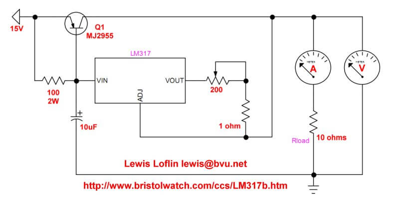
    I wanted to build this circuit:


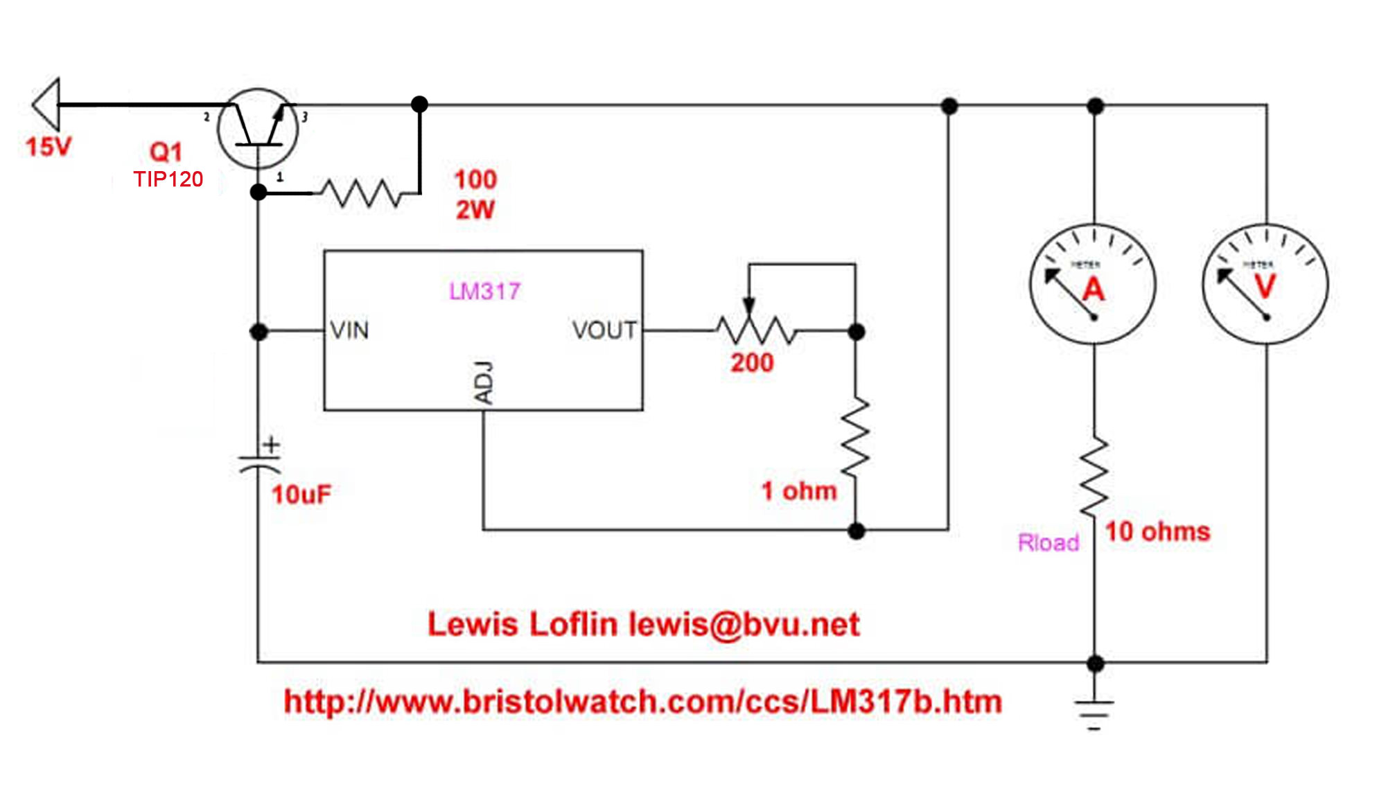
    But I didn't have a high power PNP transistor. What I do have is a TIP 120 darlington NPN, so I re did the schematic to look like this:


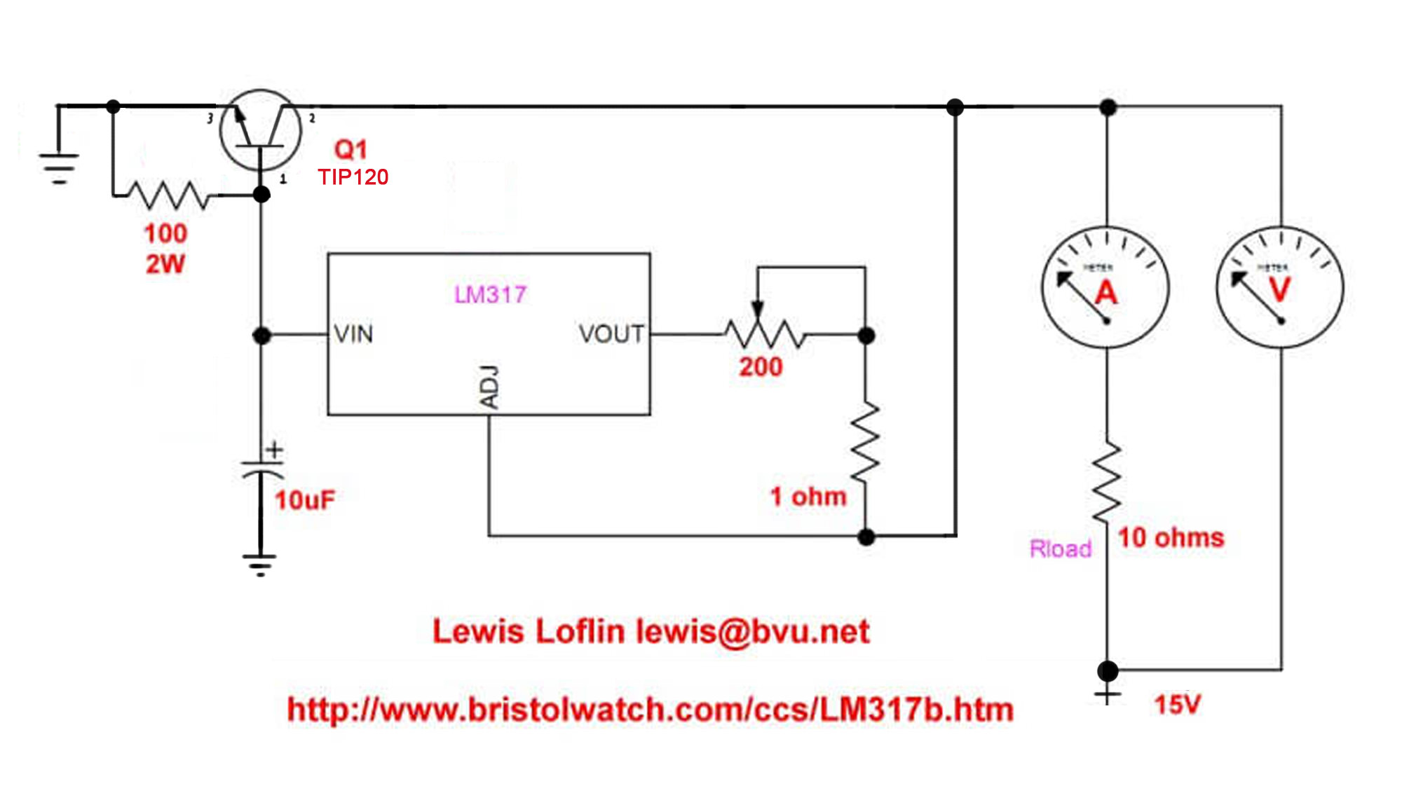
    thinking it should work, but I get nothing when I build the circuit.

    Did I do this right? Or did I make a mistake?

    #2
    Re: Replacing a PNO with NPN

    I also tried it this way and still no love:

    Comment


      #3
      Re: Replacing a PNO with NPN

      The conjugate of the original circuit is to have VIN of the LM317 hooked up to collector and the CC-wired LM317 output hooked up to the base. If you had a regular NPN it should work as-is, minus the temperature sensitivity as it depends on the characteristics of the transistor. So the circuit in #2 should work except you need to flip the LM317 subcircuit...

      However you will have to seriously modify the CC LM317's current sourcing capability to deal with the gain of the TIP120. Only took a quick look at the circuit but I suspect you will need to multiply the 200 ohm and 1 ohm resistors by around 80-100 or so (gain of the first transistor), and there is risk for oscillation due to the gain. Can you do it without using a LM317 in CC mode by using the standard current mirror circuit? The LM317 or some other voltage reference is still needed. There was a thread about this somewhere on BCN, I should have bookmarked it.

      Please CHANGE THE ATTRIBUTION that you modified the picture...these pictures, though sourced from the original author, are no longer their work. Please annotate that you changed the picture so they are not responsible for your experimental changes that don't work.

      Comment


        #4
        Re: Replacing a PNO with NPN

        what are trying to do ? its just these are test circuits initially .

        Comment


          #5
          Re: Replacing a PNO with NPN

          Originally posted by petehall347 View Post
          what are trying to do ? its just these are test circuits initially .
          I think the intent is to create a constant current source of current greater than the capability of the LM317. The LM317 provides a constant base current, so the resulting output constant current will be (β)(Ib). A Darlington complicates that because it is two transistors, so the current will be (β1)(β2)(Ib).
          PeteS in CA

          Power Supplies should be boring: No loud noises, no bright flashes, and no bad smells.
          ****************************
          To kill personal responsibility, initiative or success, punish it by taxing it. To encourage irresponsibility, improvidence, dependence and failure, reward it by subsidizing it.
          ****************************

          Comment


            #6
            Re: Replacing a PNO with NPN

            Originally posted by eccerr0r View Post
            Please CHANGE THE ATTRIBUTION that you modified the picture...these pictures, though sourced from the original author, are no longer their work. Please annotate that you changed the picture so they are not responsible for your experimental changes that don't work.
            How do I do that other than modifying the pics and re-posting? I am not able to edit my original posts.

            Comment


              #7
              Re: Replacing a PNO with NPN

              You have linked to off-site pictures, who don't you just modify them?
              "The one who says it cannot be done should never interrupt the one who is doing it."

              Comment


                #8
                Re: Replacing a PNO with NPN

                Originally posted by Per Hansson View Post
                You have linked to off-site pictures, who don't you just modify them?
                Because as soon as I do, the URL changes and I have no control over that ... its an IMGUR.COM thing...

                Comment


                  #9
                  Re: Replacing a PNO with NPN

                  You can get an NPN power transistor for the booster to work.
                  But you still need a PNP to sense when the LM317 needs help. The circuit has about a minimum 30mA output.
                  The configuration is called a compound Darlington or Sziklai named after the Hungarian EE inventor.
                  Attached Files

                  Comment


                    #10
                    Re: Replacing a PNO with NPN

                    Have to be careful when applying a darlington/sziklai pair in a position previously occupied by a simple transistor, you can see the base drive is 5KΩ which significantly reduces base current flow to offset the gain. (Note that this sample circuit is running in CV mode, so you'll have to adapt to CC.)

                    But if you have a darlington TIP120 PLUS szilkai pair up another PNP, you'll get even more gain....

                    Is the description of the modifications I suggested to make post 2 work clear, or do you need a drawing?

                    Comment

                    Working...
                    X