It's the power supply from this post – a Dell L305-00 305 Watt PSU (Lite-ON model PS-6311-2d2). Although only one capacitor appeared bulged on this PSU, I found many more that were bad.
Therefore, here goes a thread for a full recap of this PSU. The list here includes all of the electrolytic capacitors and their board designators, with the exception of the two big 200V caps on the primary side – I won't be changing these on my unit:
Cap list…
* 3.3V rail:
** [capacitor C281] OST RLP, 6.3V, 2200 uF, 10 x 20 mm
** [capacitor C282] OST RLP, 6.3V, 3300 uF, 10 x 25 mm
* 5V rail: [capacitors C202 & C203] OST RLP, 10V, 2200 uF, 10 x 25 mm
* 12V rail:
** [capacitor C221] Ltec LZP, 16V, 680 uF, 8 x 20 mm
** [capacitor C223] Ltec LZP, 16V, 2200 uF, 12.5 x 25 mm
** [capacitors C227 & C228] Taicon HG, 16V, 120 uF, 6.3 x 12 mm
* -12V rail:
** [capacitor C230]: Ltec LZP, 25V, 470 uF, 8 x 20 mm
** [capacitor C233]: Ltec LZP, 50V, 47 uF, 6.3 x 12 mm – 7912 regulator output
* 5VSB rail
** [capacitor C503]: OST RLP, 10V, 1500 uF, 10 x 20 mm
** [capacitor C504]: Ltec LZP, 10V, 470 uF, 8 x 13 mm
* Primary side aux. rail (5VSB + PWM controller Vcc) [C501]: Ltec LZP, 35V, 220 uF, 8 x 15 mm
* Main PS primary-side snubber [C123]: Ltec TY, 450V, 2.2 uF, 10 x 13 mm
* Other small caps:
** [capacitors C310, C205, C326, C222, C226, & C283]: OST RLG, 50V ,10 uF, 5 x 11 mm
** [capacitors C100 & C531]: Ltec TH, 50V, 22 uF, 5 x 11 mm
** [capacitor C307]: Ltec TH, 50V, 4.7 uF, 5 x 11 mm
** [capacitor C600]: Ltec TH, 50V, 2.2 uF, 5 x 11 mm
From these caps, I did *not* replace C227, C228, C205, C326, C222, C226, C283, C531, & C600, as I had problems with thin / small traces lifting. Thus, I was trying to avoid removing as many small caps as possible, of course without skipping anything too important (most of these aren't.)
Also, I'd like to note that the 3.3V rail and 5V rail OST RLP caps have very similar specs according to their data sheet. So for these, you can use either all 6.3V or 10V caps @ 2200 uF, if this option is easier / more convenient (i.e. buying in bulk). United Chemicon KY/KYB, Rubycon YXG, Nichicon HE, and Panasonic FC all seem to be a good match for these. Same series are also a suitable fit for Ltec LZP caps.
That said, my replacement caps were (as always ) a bit different than the original in terms of specs, but not terribly far off. They are working fine so far.
For the 5V rail, I used 2x Rubycon YXJ 10V, 2200 uF.
For the 3.3V rail, I used a Rubycon ZLH 6.3V, 2200 uF to replace the bulged 2200 uF OST RLP. The 6.3V, 3300 uF OST RLP tested fine, so I left it for the time being. I do have some 6.3V 3300 uF Chemicon KYB on hand, though, and might replace it the next time I open the PSU (which may be soon if the fan controller needs tweaking.)
For the 12V rail, I used a Chemicon KZE 16V, 680 uF cap and Chemicon LZX 16V, 2200 uF cap.
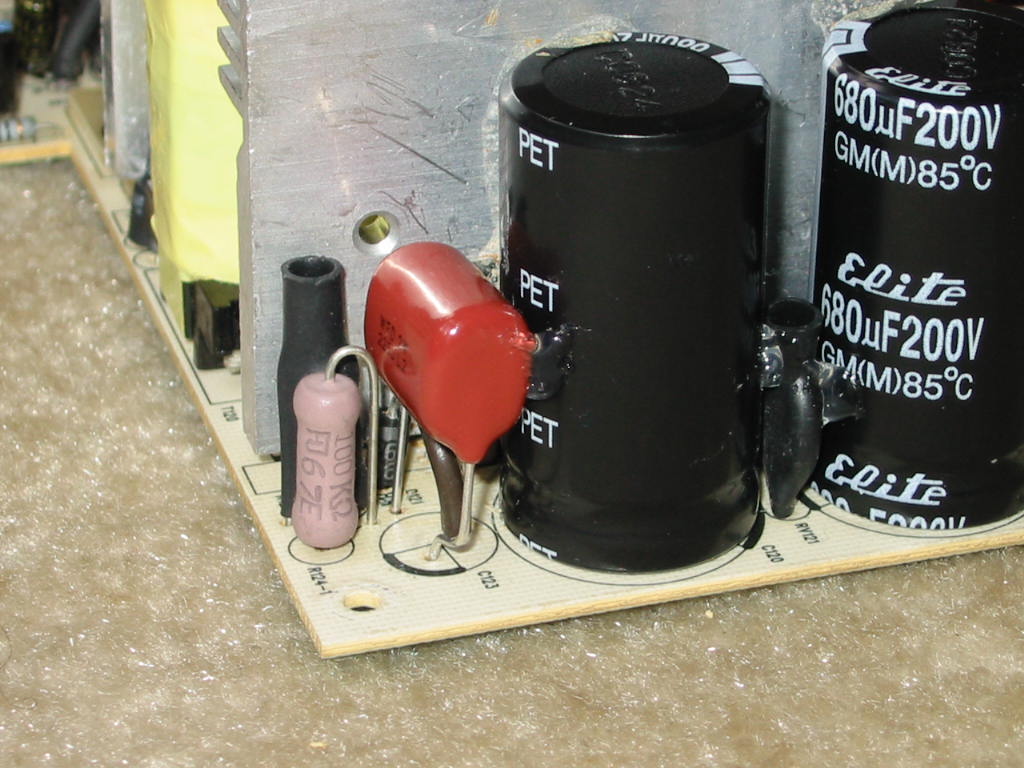
The -12V rail main filter cap (C230), I left unchanged, simply because I did not have any 25V caps in 8 mm diameter. Note that this cap is before the 7912 regulator. I found nominal voltage on it to be around -14.5V. So a 25V cap is a good idea. However, I did change C233 (Ltec LZP, 50V, 47 uF), because it was bad. I used a Nichicon PM 16V, 100 uF, 6.3x11 mm.
For the 5VSB rail, I used a Nichicon HN 16V, 1500 uF cap. Capacitor C504 (Ltec LZP, 10V, 470 uF) was bad, so I re-used C221 (Ltec LZP, 16V, 680 uF) from the 12V rail.
For C123 and C307, I used Nichicon PJ (same voltage and capacitance rating).
For C310, I used Chemicon KZE (same voltage and capacitance).
For C100, I used Nichicon PW (same voltage and capacitance).
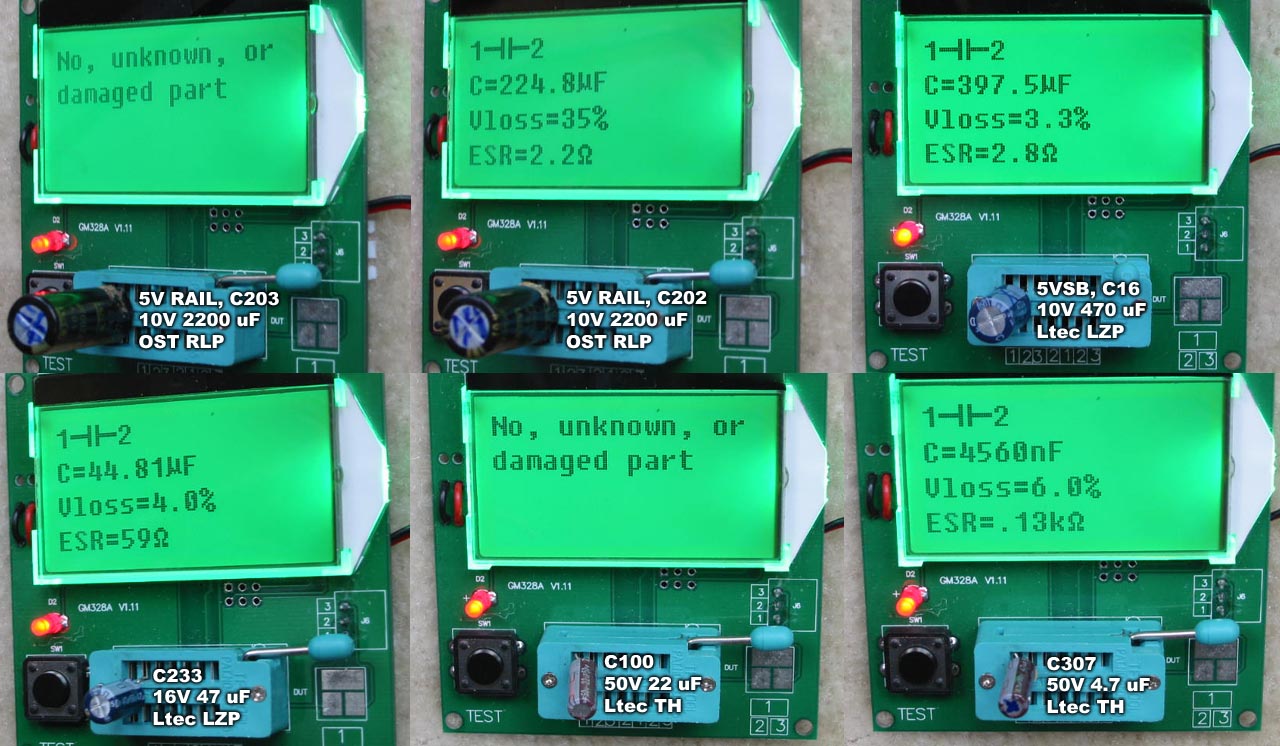
Here is the results of the recap:
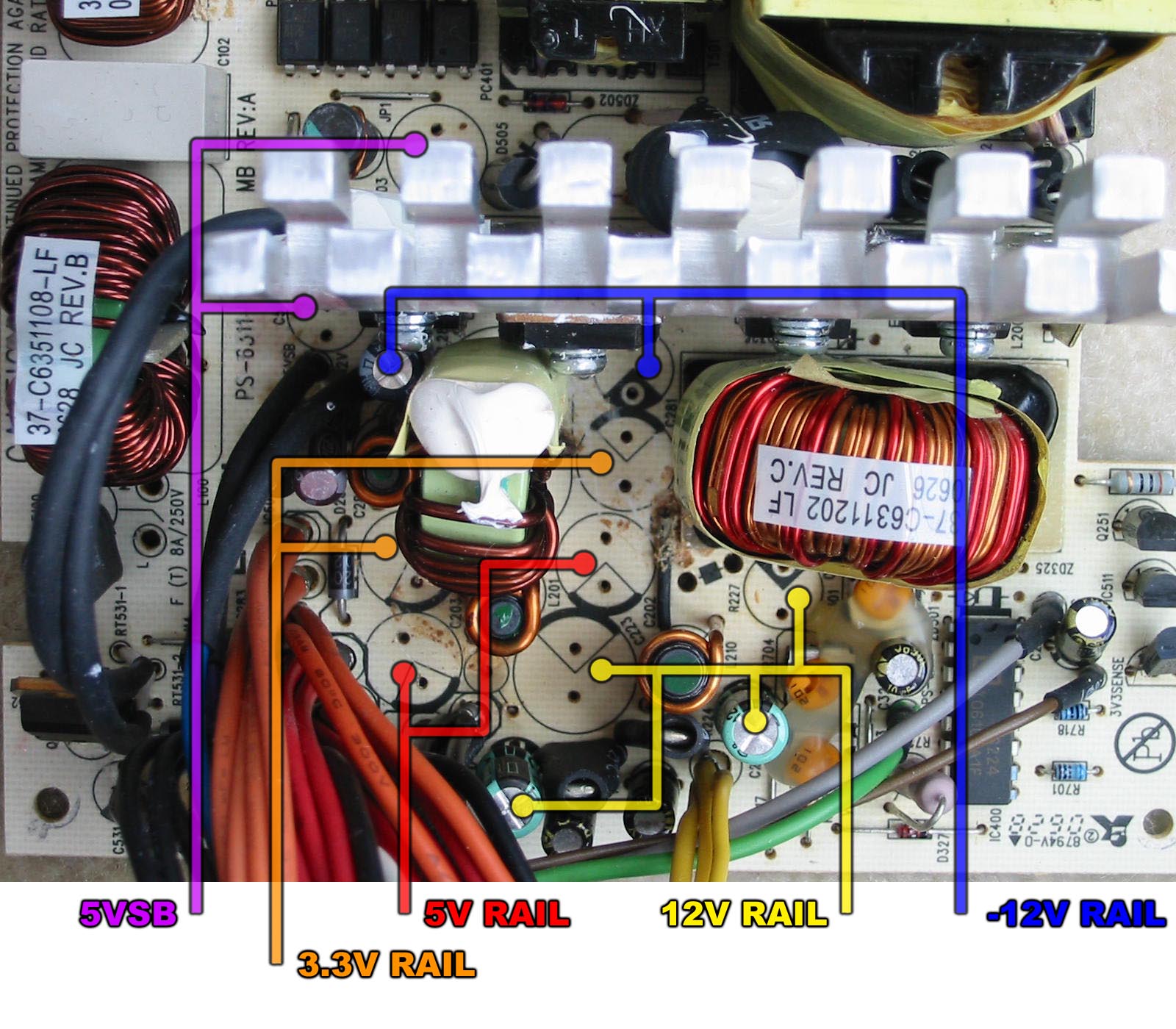
And to make it easier to see what goes where, here's also a cap diagram of the output-side capacitors.
For those of you who have this PSU and plan to do a full recap: again, be careful when you remove the small caps on the primary and secondary side – particularly those connected to thin traces. It is very easy to rip them out. I tried my best to be careful after brutally ripping one trace, and I still ended up lifting many traces. Part of it has to do because the caps had bent leads. So when I unsoldered these, they pulled the traces with them. On the last few caps, I even tried straightening the leads before pulling the cap. This helped a bit, and saved a few traces. But I still managed to damage some. As a result, I had to do some silly ugly trace repair:
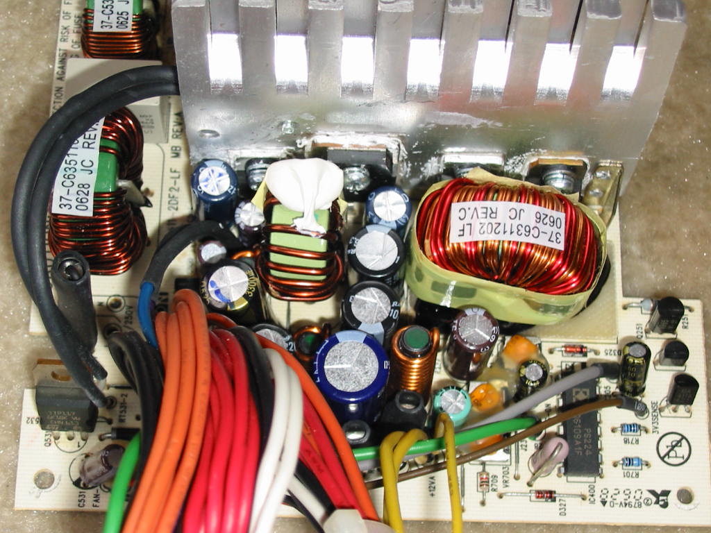
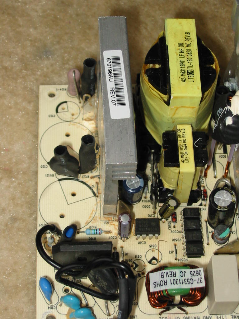
As for mods… first and foremost, I strongly suggest removing as much of the tan glue on the unit as possible, especially from the primary side and any power component's leads or anywhere it has turned brown/black. This turned out to be quite a job on my unit, because Lite-ON splurged a ton of glue in some places that were really hard to get to. One of them was behind the two 200V big caps on the primary. I had to remove them to get some of the glue cleared from the small components behind. It's a pain, but probably worth it in the long run. Here's how the primary side looked after I cleaned it (for “before” pictures, see link at the beginning of this post above):
Aside from cleaning the glue, I also strongly suggest removing dummy load resistor R223 on the 12V rail (secondary side). It is a 75-Ohm, 2-Watt resistor and being connected to 12V, it dissipates close to 2W of power! It may not seem like a lot, but it was enough to darken/burn the insulation on some of the output wires around it as well as the sleeve on the 2200 uF cap on the 12V rail. So, it is best to remove/replace this resistor. On PSUs that will be used with non-retro PCs (i.e. more 12V rail load than 5V rail), I usually replace this resistor with a 1-KOhm ¼ -Watt or skip it altogether. It's not necessarily to use that exact value, of course. If the PSU will be used with a higher 5V load, then consider putting something in the range of 270-470 Ohms with a 1 Watt rating.
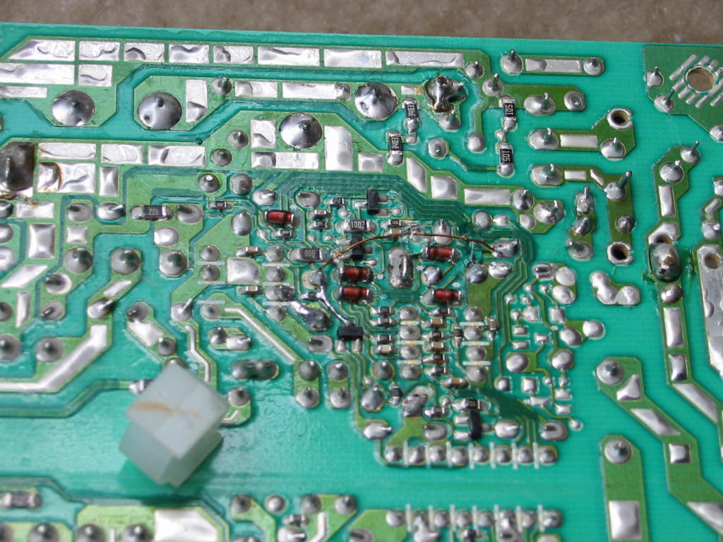
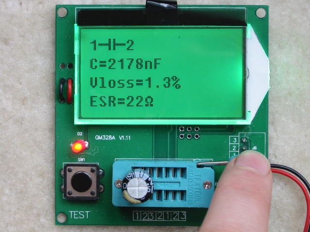
Another mod I did is replace the main PS primary-side snubber [C123] with a Polypropylene (PP) film capacitor (of same voltage and capacitance rating). Reason why is because I have never seen a snubber circuit with an electrolytic, and I don't think it's a good idea either. If/when the electrolytic snubber cap goes high-ESR, the circuit may become very ineffective at clamping inductive spikes and possibly make the voltage across the switching MOSFET on the primary side rise high enough to destroy it. In my case, C123 was just on its way out with 22 Ohms ESR, so I had to replace it.
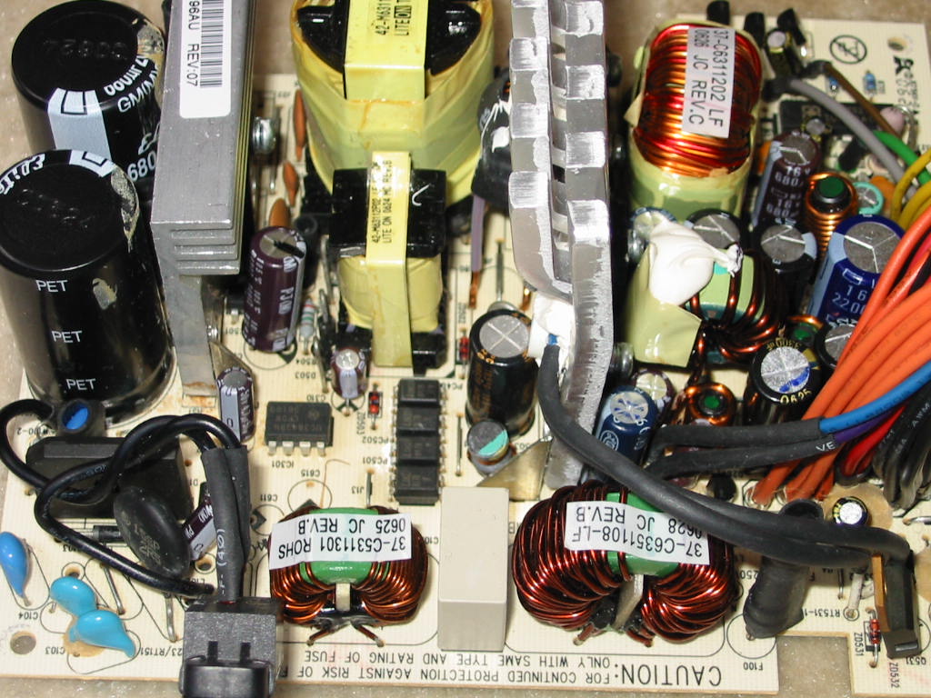
The advantage of using a non-polarized film capacitor is that it won't go high-ESR with time. I picked PP type because it has excellent stability across a wide range of temperatures and frequencies. Since the new PP cap was much wider lead spacing, I moved around some of the components in the snubber circuit to use the space a little better. They are still connected the same way as before, though. Here's a picture of the finished modded snubber circuit:
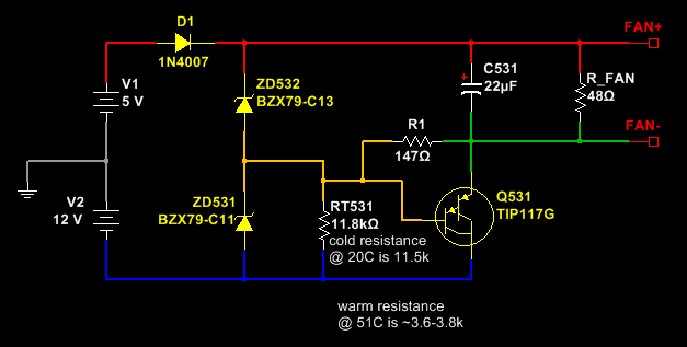
Finally, the fan controller may need a bit of tweaking. At 20°C room temperature, it only runs the fan at about 4 to 4.5V. I tried putting a potentiometer across the NTC thermistor that is responsible for changing the fan speed (attached on the secondary heatsink), but even @ 1 KOhm parallel resistance, the fan was still running at around 4.5 to 5V. And according to some temperature tests I did with my heat gun, the thermistor resistance goes down only to around 3.5~3.8 KOhms at ~50-52°C. To me, this suggests the heatsink may have to get very hot before the fan kicks in harder. And this agrees with the slight darkening of the PCB, which suggests the PSU may be running at bit hot inside. Thus, I am planning to run some more tests with my type-K temperature meter and actually see how hot the unit runs inside. If the heatsinks run over 60°C, I will definitely try modding the fan controller. That said, here is a picture of the fan controller currently:
For now, though, that's all the work I've done on this PSU. And given how long this post has become, let's say that's all for today.
Therefore, here goes a thread for a full recap of this PSU. The list here includes all of the electrolytic capacitors and their board designators, with the exception of the two big 200V caps on the primary side – I won't be changing these on my unit:
Cap list…
* 3.3V rail:
** [capacitor C281] OST RLP, 6.3V, 2200 uF, 10 x 20 mm
** [capacitor C282] OST RLP, 6.3V, 3300 uF, 10 x 25 mm
* 5V rail: [capacitors C202 & C203] OST RLP, 10V, 2200 uF, 10 x 25 mm
* 12V rail:
** [capacitor C221] Ltec LZP, 16V, 680 uF, 8 x 20 mm
** [capacitor C223] Ltec LZP, 16V, 2200 uF, 12.5 x 25 mm
** [capacitors C227 & C228] Taicon HG, 16V, 120 uF, 6.3 x 12 mm
* -12V rail:
** [capacitor C230]: Ltec LZP, 25V, 470 uF, 8 x 20 mm
** [capacitor C233]: Ltec LZP, 50V, 47 uF, 6.3 x 12 mm – 7912 regulator output
* 5VSB rail
** [capacitor C503]: OST RLP, 10V, 1500 uF, 10 x 20 mm
** [capacitor C504]: Ltec LZP, 10V, 470 uF, 8 x 13 mm
* Primary side aux. rail (5VSB + PWM controller Vcc) [C501]: Ltec LZP, 35V, 220 uF, 8 x 15 mm
* Main PS primary-side snubber [C123]: Ltec TY, 450V, 2.2 uF, 10 x 13 mm
* Other small caps:
** [capacitors C310, C205, C326, C222, C226, & C283]: OST RLG, 50V ,10 uF, 5 x 11 mm
** [capacitors C100 & C531]: Ltec TH, 50V, 22 uF, 5 x 11 mm
** [capacitor C307]: Ltec TH, 50V, 4.7 uF, 5 x 11 mm
** [capacitor C600]: Ltec TH, 50V, 2.2 uF, 5 x 11 mm
From these caps, I did *not* replace C227, C228, C205, C326, C222, C226, C283, C531, & C600, as I had problems with thin / small traces lifting. Thus, I was trying to avoid removing as many small caps as possible, of course without skipping anything too important (most of these aren't.)
Also, I'd like to note that the 3.3V rail and 5V rail OST RLP caps have very similar specs according to their data sheet. So for these, you can use either all 6.3V or 10V caps @ 2200 uF, if this option is easier / more convenient (i.e. buying in bulk). United Chemicon KY/KYB, Rubycon YXG, Nichicon HE, and Panasonic FC all seem to be a good match for these. Same series are also a suitable fit for Ltec LZP caps.
That said, my replacement caps were (as always
) a bit different than the original in terms of specs, but not terribly far off. They are working fine so far.For the 5V rail, I used 2x Rubycon YXJ 10V, 2200 uF.
For the 3.3V rail, I used a Rubycon ZLH 6.3V, 2200 uF to replace the bulged 2200 uF OST RLP. The 6.3V, 3300 uF OST RLP tested fine, so I left it for the time being. I do have some 6.3V 3300 uF Chemicon KYB on hand, though, and might replace it the next time I open the PSU (which may be soon if the fan controller needs tweaking.)
For the 12V rail, I used a Chemicon KZE 16V, 680 uF cap and Chemicon LZX 16V, 2200 uF cap.
The -12V rail main filter cap (C230), I left unchanged, simply because I did not have any 25V caps in 8 mm diameter. Note that this cap is before the 7912 regulator. I found nominal voltage on it to be around -14.5V. So a 25V cap is a good idea. However, I did change C233 (Ltec LZP, 50V, 47 uF), because it was bad. I used a Nichicon PM 16V, 100 uF, 6.3x11 mm.
For the 5VSB rail, I used a Nichicon HN 16V, 1500 uF cap. Capacitor C504 (Ltec LZP, 10V, 470 uF) was bad, so I re-used C221 (Ltec LZP, 16V, 680 uF) from the 12V rail.
For C123 and C307, I used Nichicon PJ (same voltage and capacitance rating).
For C310, I used Chemicon KZE (same voltage and capacitance).
For C100, I used Nichicon PW (same voltage and capacitance).
Here is the results of the recap:
And to make it easier to see what goes where, here's also a cap diagram of the output-side capacitors.
For those of you who have this PSU and plan to do a full recap: again, be careful when you remove the small caps on the primary and secondary side – particularly those connected to thin traces. It is very easy to rip them out. I tried my best to be careful after brutally ripping one trace, and I still ended up lifting many traces. Part of it has to do because the caps had bent leads. So when I unsoldered these, they pulled the traces with them. On the last few caps, I even tried straightening the leads before pulling the cap. This helped a bit, and saved a few traces. But I still managed to damage some. As a result, I had to do some silly ugly
trace repair:As for mods… first and foremost, I strongly suggest removing as much of the tan glue on the unit as possible, especially from the primary side and any power component's leads or anywhere it has turned brown/black. This turned out to be quite a job on my unit, because Lite-ON splurged a ton of glue in some places that were really hard to get to. One of them was behind the two 200V big caps on the primary. I had to remove them to get some of the glue cleared from the small components behind. It's a pain, but probably worth it in the long run. Here's how the primary side looked after I cleaned it (for “before” pictures, see link at the beginning of this post above):
Aside from cleaning the glue, I also strongly suggest removing dummy load resistor R223 on the 12V rail (secondary side). It is a 75-Ohm, 2-Watt resistor and being connected to 12V, it dissipates close to 2W of power!
It may not seem like a lot, but it was enough to darken/burn the insulation on some of the output wires around it as well as the sleeve on the 2200 uF cap on the 12V rail. So, it is best to remove/replace this resistor. On PSUs that will be used with non-retro PCs (i.e. more 12V rail load than 5V rail), I usually replace this resistor with a 1-KOhm ¼ -Watt or skip it altogether. It's not necessarily to use that exact value, of course. If the PSU will be used with a higher 5V load, then consider putting something in the range of 270-470 Ohms with a 1 Watt rating.Another mod I did is replace the main PS primary-side snubber [C123] with a Polypropylene (PP) film capacitor (of same voltage and capacitance rating). Reason why is because I have never seen a snubber circuit with an electrolytic, and I don't think it's a good idea either. If/when the electrolytic snubber cap goes high-ESR, the circuit may become very ineffective at clamping inductive spikes and possibly make the voltage across the switching MOSFET on the primary side rise high enough to destroy it. In my case, C123 was just on its way out with 22 Ohms ESR, so I had to replace it.
The advantage of using a non-polarized film capacitor is that it won't go high-ESR with time. I picked PP type because it has excellent stability across a wide range of temperatures and frequencies. Since the new PP cap was much wider lead spacing, I moved around some of the components in the snubber circuit to use the space a little better. They are still connected the same way as before, though. Here's a picture of the finished modded snubber circuit:
Finally, the fan controller may need a bit of tweaking. At 20°C room temperature, it only runs the fan at about 4 to 4.5V. I tried putting a potentiometer across the NTC thermistor that is responsible for changing the fan speed (attached on the secondary heatsink), but even @ 1 KOhm parallel resistance, the fan was still running at around 4.5 to 5V. And according to some temperature tests I did with my heat gun, the thermistor resistance goes down only to around 3.5~3.8 KOhms at ~50-52°C. To me, this suggests the heatsink may have to get very hot before the fan kicks in harder. And this agrees with the slight darkening of the PCB, which suggests the PSU may be running at bit hot inside. Thus, I am planning to run some more tests with my type-K temperature meter and actually see how hot the unit runs inside. If the heatsinks run over 60°C, I will definitely try modding the fan controller. That said, here is a picture of the fan controller currently:
For now, though, that's all the work I've done on this PSU. And given how long this post has become, let's say that's all for today.
Attached Files
Comment