Announcement

Collapse
No announcement yet.

Best practice for soldering a Flyback Transformer

Collapse
X
 
  • Filter
  • Time
  • Show
Clear All
new posts

    Best practice for soldering a Flyback Transformer

    I'm trying to solder a flyback transformer back to its board. It is quite heavy and the PCB is battered by age.

    Well:
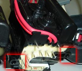
    There are at least 8 solderable pins and two screws which secures (or at least on paper, please read below) the transformer onto the PCB.

    This is a reference picture:


    I already had to reflow some pins once.

    Who do you guys think would provide the less stress for the pins?
    1) Screwing the transformer onto the PCB and then solder;
    2) Solder the pins and then screw the transformer

    #2
    Re: Best practice for soldering a Flyback Transformer

    screw it first

    Comment


      #3
      Re: Best practice for soldering a Flyback Transformer

      Some of those pins along with land areas of the pcb will have high a thermal mass, aim for the lowest temperature for soldering if the copper lands are damaged. As a side note you need to ensure your soldering system has good thermal reserve so you are able to complete the rework in a timely manner, goes without saying used leaded solder.

      Comment


        #4
        Re: Best practice for soldering a Flyback Transformer

        Would it be better to screw it first?

        Comment


          #5
          Re: Best practice for soldering a Flyback Transformer

          Screw the flyback to the board then solder the pins.

          Comment


            #6
            Re: Best practice for soldering a Flyback Transformer

            Thank you.

            Having a hard time even fitting it with screws (it lays unevenly, one side with more distance between trafo and board). No wonder it developed bad solder joints.

            I am afraid that everytime you move that CRT some solder points takes a lot of fatigue according to inclination angle of the monitor itself. Very strange since other monitors are just better (just solder, greater pads, not screws but sturdy plastic hooks).

            Been thinking about adding grommets on one side and add epoxy on the center, between trafo and PCB, which is quite frustrating and will make it unrepairable in the future. Not to count that it takes hours for epoxy to cure.

            Any suggestion is warmly welcomed.
            Last edited by Hitto; 01-14-2020, 06:20 PM.

            Comment


              #7
              Re: Best practice for soldering a Flyback Transformer

              Is this the original flyback transformer or a replacement? Did it originally have mounting screws or was it just held in place by the pins?

              It is not uncommon to have poor solder connections on a flyback, or any transformer etc. Due to the larger pins they don't always get enough solder when they are manufactured. and since they have a larger mass and do vibrate at the horz. frequency the connecions get loose over time.

              Comment

              Working...
              X