Thank you to the guys at HEGE supporting Badcaps [ HEGE ] [ HEGE DEX Chart ]

Announcement

Collapse
No announcement yet.

Samsung SMPS

Collapse
X
 
  • Filter
  • Time
  • Show
Clear All
new posts

    Samsung SMPS

    I have a SMPS from a Samsung AV receiver. It had a blown fuse, high voltage capacitor and power FET. I have since replaced those and it now turns on, but goes into protection mode and shuts down.
    I noticed that I am missing the 43v output and the 4v rail is putting out 30 volts. All the other voltages check fine.
    Can someone point me in the right direction on what to test?
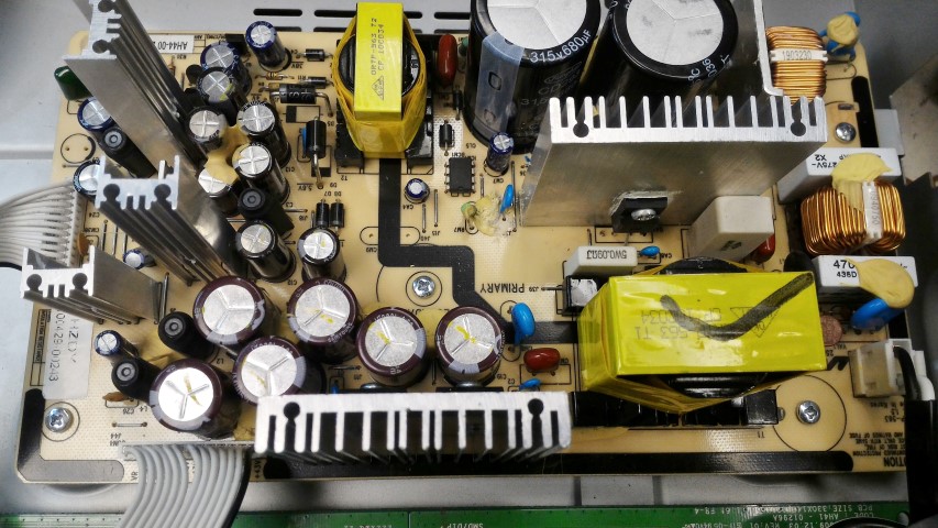
    Attached Files
    Last edited by Burned; 03-28-2018, 02:25 PM.

    #2
    Re: Samsung SMPS

    Model number of the Receiver?
    What is the P/N of the power supply board.
    Are you 100% sure that you are getting 30 at the 4V rail? I would expect parts to blow up badly when such high Voltage being applied to the circuit that expecting only 4V.
    Please up load the straight shot hi-res pictures of the top and bottom side of this power supply board.
    Last edited by budm; 03-28-2018, 03:45 PM.
    Never stop learning
    Basic LCD TV and Monitor troubleshooting guides.
    http://www.badcaps.net/forum/showthr...956#post305956

    Voltage Regulator (LDO) testing:
    http://www.badcaps.net/forum/showthr...999#post300999

    Inverter testing using old CFL:
    http://www.badcaps.net/forum/showthr...er+testing+cfl

    Tear down pictures : Hit the ">" Show Albums and stories" on the left side
    http://s807.photobucket.com/user/budm/library/

    TV Factory reset codes listing:
    http://www.badcaps.net/forum/showthread.php?t=24809

    Comment


      #3
      Re: Samsung SMPS

      SMPS P/N AH44-00 218A(110V)

      I am not sure of the model number, its not on the unit. I think its on labelled on the DVD player, which is not with me.

      The output on the board has it marked as +4V and -4V. They are both testing around -30 volts when on. I noticed the capacitors in that circuit are 25v.


      Attached Files

      Comment


        #4
        Re: Samsung SMPS

        I had a unit with the same problem repaired. Check to see if it outputs 3.3V. If not replace the LDO regulator. It's the one next to C17 if I remember correctly.

        Comment


          #5
          Re: Samsung SMPS

          I have searched for a schematic but can find any maybe see if you can find the samsung model number your working on

          all the info i can find so far is its a Samsung AH44-00294A PCB-POWER SUPPLY, AV HTS SMPS, V300SA_DSM

          Comment


            #6
            Re: Samsung SMPS

            Check what the -38 volts is (reference to ground), then check the 4 volts by not using ground but by checking across +4 and -4 pins. Also the power supply may need a load on one of the supplies if the power supply has over voltage protection.
            Last edited by R_J; 03-29-2018, 03:43 PM.

            Comment


              #7
              Re: Samsung SMPS

              This schematic is for a AH44-00114A which might be helpfull
              Attached Files

              Comment


                #8
                Re: Samsung SMPS

                Originally posted by R_J View Post
                Check what the -38 volts is (reference to ground), then check the 4 volts by not using ground but by checking across +4 and -4 pins. Also the power supply may need a load on one of the supplies if the power supply has over voltage protection.
                The -36 volt output is reading what it should be. All of the outputs on that connector are good except for the 4 volt circuit. The 4 volt circuit is reading -32 volts on both +/-. When I read across the two (+/- 4 v) I get 3.2 volts.

                The other output connector is missing +/-43 volts. Do those transformers have a thermal fuse? I dont think I am getting anything from that large transformer that should be supplying 43 volts.

                Comment


                  #9
                  Re: Samsung SMPS

                  To me it looks like this DVD player has Vacuum Fluorescent Displays - VFD, so the the +/-4V is for the filament and it is not reference to GND, and the -36V is also for the VFD.
                  You have two connectors on the cold side but you only show picture of just one of them, we need to see the other connector and its pin labels too.
                  The +/- 43V power supply probably needs PS-ON from controller board for it to come on so check the DC V on that 'PS' pin when you toggle the power switch to see if it changes state or not.
                  We also need the pictures showing all the boards and how they are connected, but we do need the model number of this product we are trying to help. The more details information we have the easier for us to troubleshoot from long distant due to not having the unit in front of us to look at.
                  VFD operation:
                  https://www.noritake-elec.com/techno.../vfd-operation
                  Last edited by budm; 03-30-2018, 10:12 AM.
                  Never stop learning
                  Basic LCD TV and Monitor troubleshooting guides.
                  http://www.badcaps.net/forum/showthr...956#post305956

                  Voltage Regulator (LDO) testing:
                  http://www.badcaps.net/forum/showthr...999#post300999

                  Inverter testing using old CFL:
                  http://www.badcaps.net/forum/showthr...er+testing+cfl

                  Tear down pictures : Hit the ">" Show Albums and stories" on the left side
                  http://s807.photobucket.com/user/budm/library/

                  TV Factory reset codes listing:
                  http://www.badcaps.net/forum/showthread.php?t=24809

                  Comment


                    #10
                    Re: Samsung SMPS

                    If the -36 volts is ok then that part of the supply is working fine, To measure the 4 volts DO NOT USE GROUND. measure across the (-) 4 volt and (+) 4 volt pins.
                    What are the pin designations on that other plug? I suspect the pin I marked could be the pin that turns on that part of the supply. That supply would power the audio outputs and is only turned on when the unit is tirned on. I suspect if you put the power supply in the unit it will work.
                    Attached Files
                    Last edited by R_J; 03-30-2018, 10:55 AM.

                    Comment


                      #11
                      Re: Samsung SMPS

                      When I plug the other output (43v) into the board it goes into protection mode then shutdowns shortly after turning it on.


                      Still waiting for my friend to get me the model number off of the DVD player.

                      Thank you for all the help guys.
                      Attached Files

                      Comment


                        #12
                        Re: Samsung SMPS

                        It is likely you have a shorted audio mosfet in the output that is loading the +/- 43 volts
                        It seems to be a Samsung Model HW-C500 or C700, Manual is here https://elektrotanya.com/samsung_hw_.../download.html
                        Last edited by R_J; 03-30-2018, 12:50 PM.

                        Comment


                          #13
                          Re: Samsung SMPS

                          Originally posted by R_J View Post
                          It is likely you have a shorted audio mosfet in the output that is loading the +/- 43 volts
                          It seems to be a Samsung Model HW-C500 or C700, Manual is here https://elektrotanya.com/samsung_hw_.../download.html
                          You're right. I took the mainboard out and it says HW C500/C700 on the bottom.

                          Comment


                            #14
                            Re: Samsung SMPS

                            Originally posted by budm View Post
                            To me it looks like this DVD player has Vacuum Fluorescent Displays - VFD, so the the +/-4V is for the filament and it is not reference to GND, and the -36V is also for the VFD.
                            You have two connectors on the cold side but you only show picture of just one of them, we need to see the other connector and its pin labels too.
                            The +/- 43V power supply probably needs PS-ON from controller board for it to come on so check the DC V on that 'PS' pin when you toggle the power switch to see if it changes state or not.
                            We also need the pictures showing all the boards and how they are connected, but we do need the model number of this product we are trying to help. The more details information we have the easier for us to troubleshoot from long distant due to not having the unit in front of us to look at.
                            VFD operation:
                            https://www.noritake-elec.com/techno.../vfd-operation
                            PS-ON goes up to 3.2v when the power is turned on.

                            Comment


                              #15
                              Re: Samsung SMPS

                              With everything hooked back up I get 3.2v at PS_ON. I still do not have +/- 43v out of the other connector to the main board.
                              I do have a blue ring tester, maybe I should check the larger transformer that supplies the 43v. I have read that some transformers can have thermal fuses inside.
                              I dont know what to check next

                              Comment


                                #16
                                Re: Samsung SMPS

                                I doubt there is a thermal fuse in that transformer or that it is bad. Check the voltage on the primary(B+) then check the voltage on the drain of QA1, Check the resistance of RA8, should check like a short (.05 ohm) If theis resistor is open, QA1 likely shorted.
                                Then check the voltage on DM4 Cathode then Q10 collector and emitter, then ICA1, Vcc pin. You need vcc on pin 7 of this ic for it to work, The voltaage should be greater than 10 volts, liely around 18 volts. also check the voltage on FB pin

                                Have you downloaded the service manual for this model?
                                Last edited by R_J; 04-02-2018, 08:44 PM.

                                Comment


                                  #17
                                  Re: Samsung SMPS

                                  Originally posted by R_J View Post
                                  Have you downloaded the service manual for this model?
                                  Yes I have. Thank you for that.

                                  I will test all those you mentioned.

                                  Comment


                                    #18
                                    Re: Samsung SMPS

                                    Originally posted by R_J View Post
                                    I doubt there is a thermal fuse in that transformer or that it is bad. Check the voltage on the primary(B+) then check the voltage on the drain of QA1, Check the resistance of RA8, should check like a short (.05 ohm) If theis resistor is open, QA1 likely shorted.
                                    Then check the voltage on DM4 Cathode then Q10 collector and emitter, then ICA1, Vcc pin. You need vcc on pin 7 of this ic for it to work, The voltaage should be greater than 10 volts, liely around 18 volts. also check the voltage on FB pin

                                    Have you downloaded the service manual for this model?
                                    I cant find a that diode or transistor DM4, Q10
                                    166v on B+
                                    332v QA1 drain
                                    ICA1 has 2.3v on pin 7

                                    Comment


                                      #19
                                      Re: Samsung SMPS

                                      Looks like the schematic might not match the power supply in that unit.
                                      Do you have + and - 12 volts on con4 ?

                                      If you measure 332v on Qa1 drain, it looks like the circuit is working??? and you should have +/- 40
                                      Check the voltages on ic5 (ic3 on schematic) That looks like some kind of protection circuit.
                                      I still think there could be a fault with the audio outputs and the +/- 40 is in protection.
                                      Last edited by R_J; 04-03-2018, 06:14 PM.

                                      Comment


                                        #20
                                        Re: Samsung SMPS

                                        1) Measure the resistance between GND pin and +43V pin.
                                        2) Measure the resistance between GND pin and -43V pin.
                                        3) Measure the resistance between -43V pin and +43V pin.
                                        Report the readings.
                                        Never stop learning
                                        Basic LCD TV and Monitor troubleshooting guides.
                                        http://www.badcaps.net/forum/showthr...956#post305956

                                        Voltage Regulator (LDO) testing:
                                        http://www.badcaps.net/forum/showthr...999#post300999

                                        Inverter testing using old CFL:
                                        http://www.badcaps.net/forum/showthr...er+testing+cfl

                                        Tear down pictures : Hit the ">" Show Albums and stories" on the left side
                                        http://s807.photobucket.com/user/budm/library/

                                        TV Factory reset codes listing:
                                        http://www.badcaps.net/forum/showthread.php?t=24809

                                        Comment

                                        Working...
                                        X