Many of you are probably already familiar with the high ripple and noise the FSP Epsilon design can produce under heavy load. jonnyGURU has documented the issue several times.
I have one of these sitting before me, and would like to take a stab at cleaning up the output somewhat by upgrading the caps in it. I'm going to be concentrating mostly on the 12v rail, which is serviced by OST caps, but will probably replace the others as well.
From what I can tell of the design, this thing uses two OST 2200uF caps in parallel to filter the 12v output. However, I'm not sure if there's a proper pi filter in here... there's a third OST of that value, but it connects to the smaller of the two coils that runs to the 5v and 3.3v section. It actually looks like there's a pi filter for the two lower voltages, but not for 12v. I could be wrong though - I'll post a pic.
My question is, would higher values in good quality caps on the 12v output be likely to improve the ripple situation? I was thinking I'd move to 2700uF if I can get them in there.
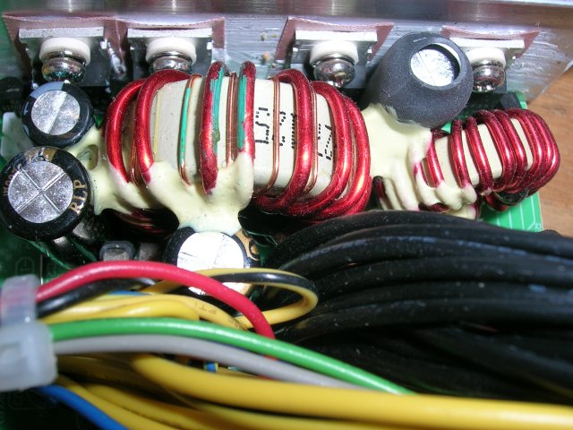
This pic shows all three OST's - one is the one wrapped in heatshrink.
I have one of these sitting before me, and would like to take a stab at cleaning up the output somewhat by upgrading the caps in it. I'm going to be concentrating mostly on the 12v rail, which is serviced by OST caps, but will probably replace the others as well.
From what I can tell of the design, this thing uses two OST 2200uF caps in parallel to filter the 12v output. However, I'm not sure if there's a proper pi filter in here... there's a third OST of that value, but it connects to the smaller of the two coils that runs to the 5v and 3.3v section. It actually looks like there's a pi filter for the two lower voltages, but not for 12v. I could be wrong though - I'll post a pic.
My question is, would higher values in good quality caps on the 12v output be likely to improve the ripple situation? I was thinking I'd move to 2700uF if I can get them in there.
This pic shows all three OST's - one is the one wrapped in heatshrink.
Attached Files
Comment