Announcement

Collapse
No announcement yet.

Corsair GS800 Power Supply Problem

Collapse
X
 
  • Filter
  • Time
  • Show
Clear All
new posts

    Corsair GS800 Power Supply Problem

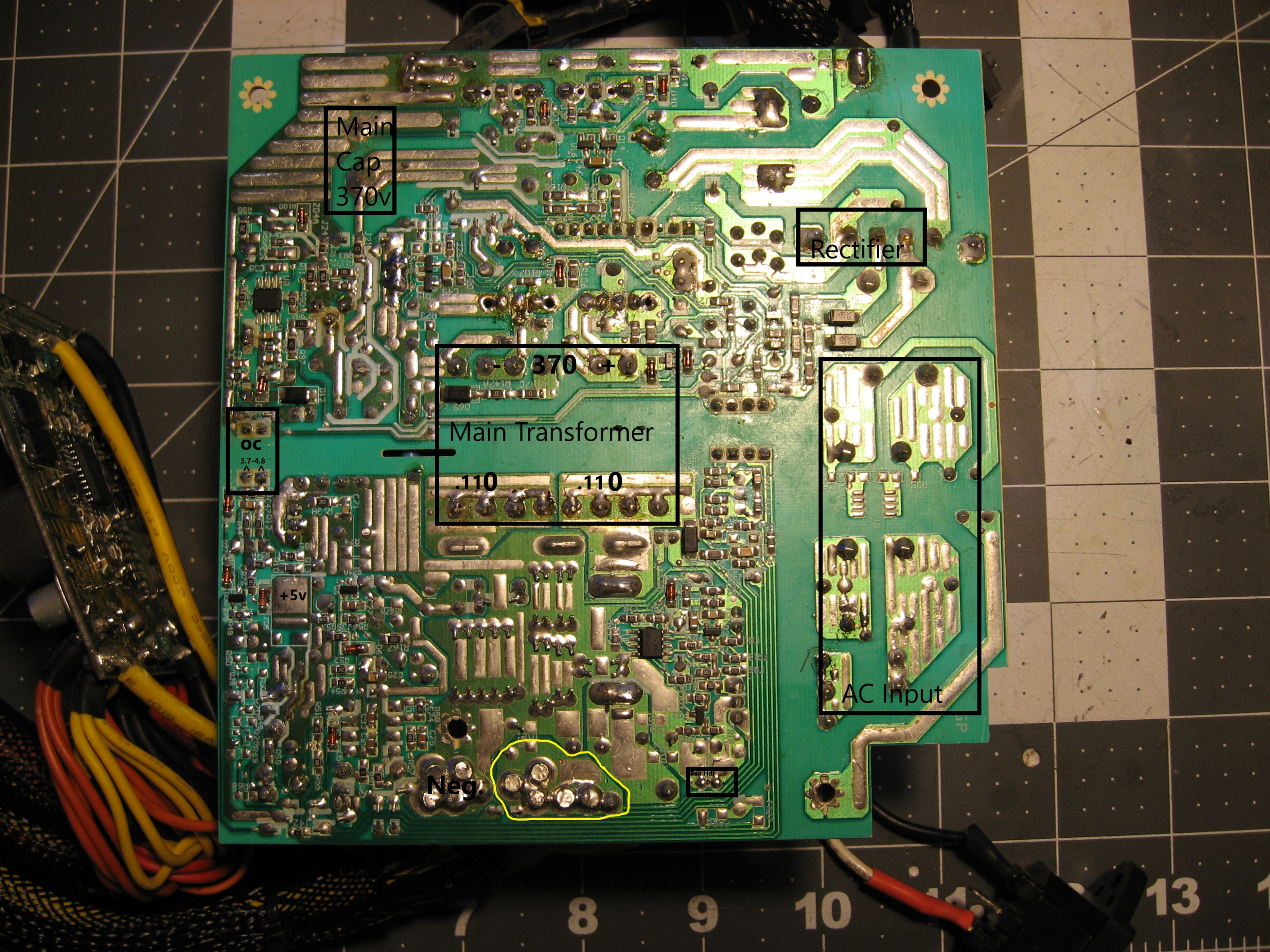
    Had this thing laying around for a bit so I thought I would drag it out under the current global circumstances and see if I can repair it. I have recorded my readings on the image below indicating basic layout and some voltage readings. I am not an EE but I know NOT to mess with the large cap.

    EDIT: Cathode is top terminal of Main Cap.

    All votlages taken on secondary side were to ground or "neg" in the image.

    Essentially the primary side is charging to 370ish. I do have 5v on pin 11.

    Grounding pin 4 (green) while small fan and two SATA drives are connected for a load while probing.

    Visually I cant see anything that looks out of the ordinary. The empty holes on the primary side were sucked out inspecting they are n/c by design.

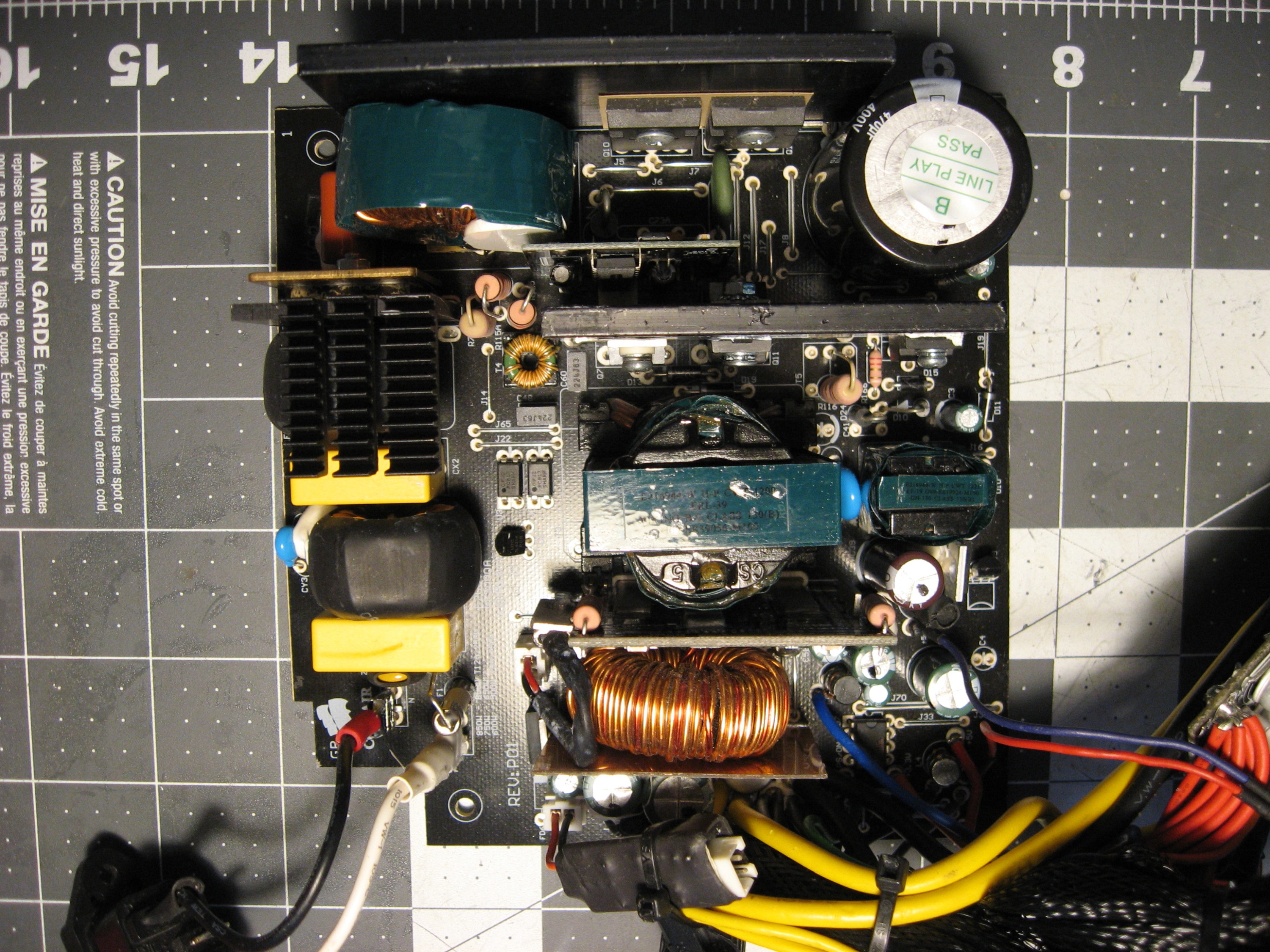
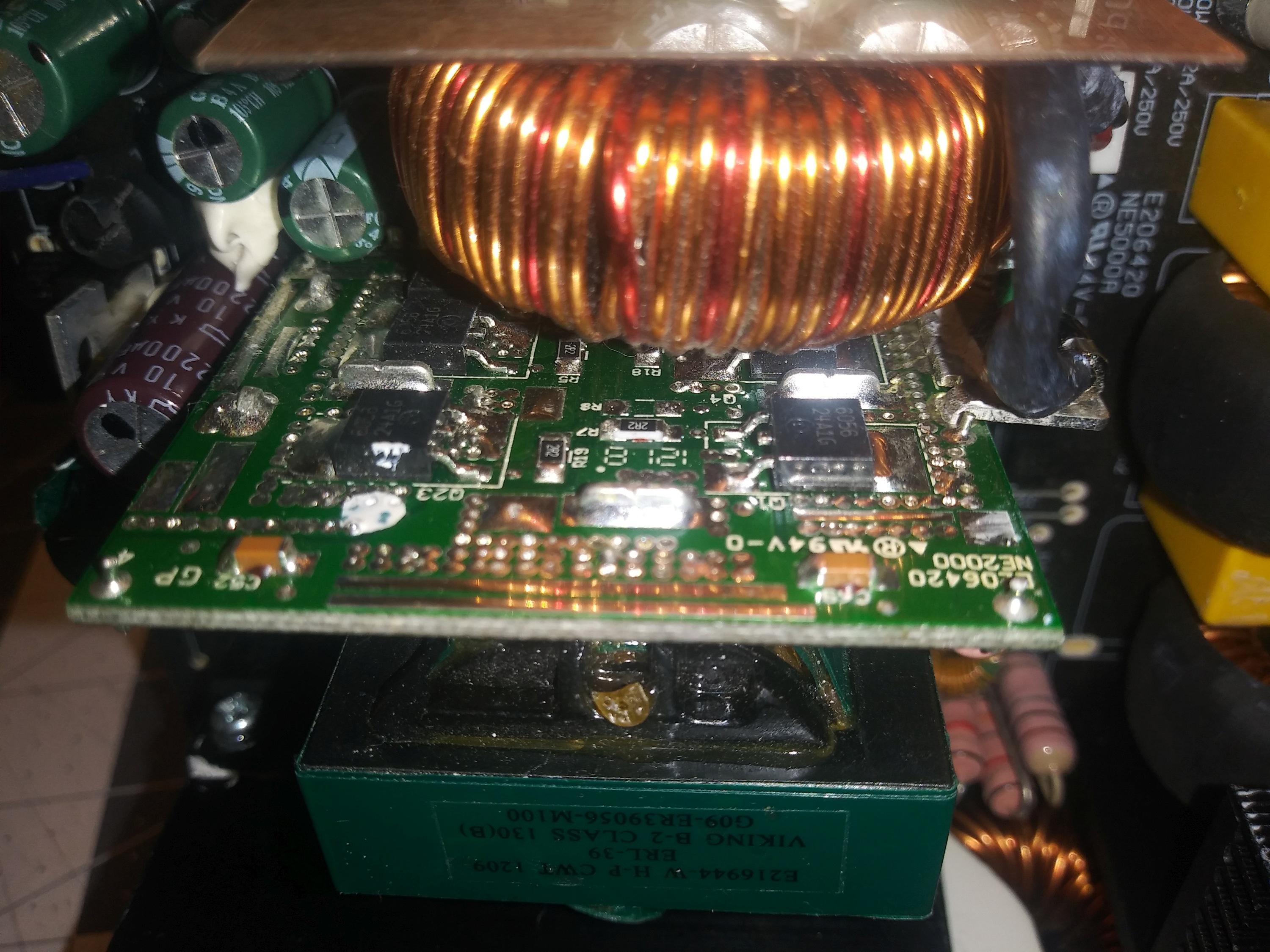
    Anyone have any ideas where I might look given this information? I have not looked at the small vertical board (image below).


    Attached Files
    Last edited by Per Hansson; 04-10-2020, 03:46 AM. Reason: Offsite images uploaded

    #2
    Re: Corsair GS800 Power Supply Problem

    Here are the results of what I am getting on the 24 pin connector.

    1. .0001 | 13. .0001
    2. .0001 | 14. -.0776
    3. - | 15. -
    4. .0027 | 16. ps/on
    5. - | 17. -
    6. .0027 | 18. - (probe)
    7. - | 19. -
    8. .00057 | 20 n/p
    9. 5.069 | 21. .0027
    10 .11~.14* | 22. .0026
    11. .13 | 23. .0022
    12. .0001 | 24. -

    * Pin 10 is fluctuating between .11xx and .14xx.

    It seems as if something is holding the 12v low and not allowing it to power on.

    EDIT: Found a P/S Supervisor WT7502 that "provides protection circuits, power good output (PGO), fault protection latch (FPOB), and a protection detector function (PSONB) control. It can minimize external components of switching power supply systems in personal computer.

    Probing this chip (U7) while in on state it is not getting the proper signals. PGI-power good input signal should be 1.16-1.24 volts and it is only .0153, so the problem w/ the power supply is likely before this "supervisor."
    Last edited by ShortCircuited; 04-03-2020, 12:16 PM.

    Comment


      #3
      Re: Corsair GS800 Power Supply Problem

      This diagram suggests the secondary side is not sending a signal to the primary to provide power to the transformer for 12 volts?


      Anode-Cathode drop is 1.08v according to DMM.

      Attached Files
      Last edited by Per Hansson; 04-10-2020, 03:50 AM. Reason: Offsite image uploaded

      Comment


        #4
        Re: Corsair GS800 Power Supply Problem

        To start off, I’d check if any of them secondary voltage rails is shorted. Also check the main filter capacitor for 380VDC.

        Comment


          #5
          Re: Corsair GS800 Power Supply Problem

          Thanks for the suggestion...

          Main cap is charging to 375.

          Readings to ground (secondary side):

          12v (yellow) - Meter goes OL after a second or two.
          5v (red) - 140 ohm
          3v (orange) - 126 ohm

          5v and 3 v seem kinda low...?
          Last edited by ShortCircuited; 04-03-2020, 08:35 PM.

          Comment


            #6
            Re: Corsair GS800 Power Supply Problem

            Seems OK, I supplied 12v to secondary side and current was normal with the two HDs and a small cooling fan fora test load, about 1 amp. Heated the thermistor for the fan control and the cooling fan kicked on and off.

            Voltage regulators seem fine too. When 12v is applied to the secondary via separate PS the 5v and 3.3 are present and fine.

            WT7502 (U7) is getting 4.4v for startup signal according to spec sheet 3.6v is typical. This supervisor is looking suspect. "OL" from Vcc to GND. Anyone have a value for this supervisor between pins 2 and 7?
            Last edited by ShortCircuited; 04-04-2020, 12:07 PM.

            Comment


              #7
              Re: Corsair GS800 Power Supply Problem

              Originally posted by ShortCircuited View Post
              Seems OK, I supplied 12v to secondary side and current was normal with the two HDs and a small cooling fan fora test load, about 1 amp. Heated the thermistor for the fan control and the cooling fan kicked on and off.

              Voltage regulators seem fine too. When 12v is applied to the secondary via separate PS the 5v and 3.3 are present and fine.

              WT7502 (U7) is getting 4.4v for startup signal according to spec sheet 3.6v is typical. This supervisor is looking suspect. "OL" from Vcc to GND. Anyone have a value for this supervisor between pins 2 and 7?
              The VOLTAGE between pins 2 and 7 should be around 12 volts. what do you mean by OL? are you measuring the resistance between vcc & ground? Is that what your meter displays when the probes are shorted together?

              Comment


                #8
                Re: Corsair GS800 Power Supply Problem

                Originally posted by R_J View Post
                The VOLTAGE between pins 2 and 7 should be around 12 volts. what do you mean by OL? are you measuring the resistance between vcc & ground? Is that what your meter displays when the probes are shorted together?
                Retest and resistance is 1.7kohm between vcc and gnd (2/7).

                FPOB-Fault Protection is .38v to ground and 39 megaohms to ground.
                Last edited by ShortCircuited; 04-04-2020, 12:49 PM.

                Comment


                  #9
                  Re: Corsair GS800 Power Supply Problem

                  That resistance is ok, the ic gets it vcc when the power supply is working, If there is no +12v then U7 is not the problem. Check the primary switching transistors. It looks like the pfc circuit is working as you have 380vdc, but the main primary switcher is not.
                  It looks like there are two fets in the primary, have you checked them?
                  Last edited by R_J; 04-04-2020, 12:50 PM.

                  Comment


                    #10
                    Re: Corsair GS800 Power Supply Problem

                    Originally posted by R_J View Post
                    That resistance is ok, the ic gets it vcc when the power supply is working, If there is no +12v then U7 is not the problem. Check the primary switching transistors. It looks like the pfc circuit is working as you have 380vdc, but the main primary switcher is not.
                    It looks like there are two fets in the primary, have you checked them?

                    Thanks for the suggestion. These two FETs you mentioned are Q10 and Q15 and are 6R190E6s (TO247 package) for which I cannot find the datasheet so I am consulting a C6 datasheet.

                    The drains are jumping around erratically between 138 and 172ish according to my DMM (UT61E) on both FETs.

                    The glass diodes (D37 and D40)s (circled yellow) are both 5.6ohm. Why are D37 and D40 (circled yellow) in parallel with a 4.7ohm resistor? What good are the diodes if they are essentially shorted?

                    I believe I have the pinout correctly labeled on he two FETs-
                    Attached Files
                    Last edited by Per Hansson; 04-10-2020, 03:46 AM. Reason: Offsite image uploaded

                    Comment


                      #11
                      Re: Corsair GS800 Power Supply Problem

                      Those are likely in the gate drive circuit, they are used to modify the turn on and turn off of the fets during operation. that is normal. Those might be the pfc mosfets, The one (or two) I refered to are (Q11?) the ones that drive the transformer.
                      Those type of meters (UT61E) being lower cost, will be confused by the 20~40khz high frequency signal that is on the pfc mosfets.

                      Remember the pfc boost circuit is working. The raw dc voltage on the main capacitor would be 160vdc, but the pfc is boosting it to 380vdc.
                      Last edited by R_J; 04-04-2020, 03:59 PM.

                      Comment


                        #12
                        Re: Corsair GS800 Power Supply Problem

                        Originally posted by R_J View Post
                        Those are likely in the gate drive circuit, they are used to modify the turn on and turn off of the fets during operation. that is normal. Those might be the pfc mosfets, The one (or two) I refered to are (Q11?) the ones that drive the transformer.
                        Those type of meters (UT61E) being lower cost, will be confused by the 20~40khz high frequency signal that is on the pfc mosfets.

                        Remember the pfc boost circuit is working. The raw dc voltage on the main capacitor would be 160vdc, but the pfc is boosting it to 380vdc.

                        There are a pair of 20N60S1s (TO220) physically closer to the main transformer and are labeled Q11 and Q7. You have schematic?

                        380V

                        I do have a DSO138, but I can't find it useful for anything. I dont think it can handle the voltage to be of any use here. EDIT: 50v 200khz max.
                        Last edited by ShortCircuited; 04-04-2020, 05:21 PM.

                        Comment


                          #13
                          Re: Corsair GS800 Power Supply Problem

                          I don't have a schematic, I am using your picture of the board. When checkiing voltage on the primary side, use the main filter cap (-) for meter ground, then check the voltage on D13 cathode (white mark) and D13 anode and D19 cathode and anode. D19 anode should be close to 0 or ground, if it is not, check R116 it could be open
                          Last edited by R_J; 04-04-2020, 05:46 PM.

                          Comment


                            #14
                            Re: Corsair GS800 Power Supply Problem

                            I have had the entire heatsink (HS3) out and replaced Q7 it appears. Had this PS for a while now. Did a test with a small fan and these FETs worked it seems or I would not have reinstalled it. The CM6800 (not showing short) is very near on the adjacent vertical board.

                            LOL I was about to start begging for a copy.
                            Last edited by ShortCircuited; 04-04-2020, 05:42 PM.

                            Comment


                              #15
                              Re: Corsair GS800 Power Supply Problem

                              Originally posted by R_J View Post
                              ...check the voltage on D13 cathode (white mark) and D13 anode and D19 cathode and anode. D19 anode should be close to 0 or ground, if it is not, check R116 it could be open
                              D13*:cathode 377v and anode -.19. *Traced to transformer.
                              R116: 1ohm (in and out of circuit).

                              So it looks like you are correct no grounding /switching of main transformer on primary side.
                              Last edited by ShortCircuited; 04-04-2020, 07:12 PM.

                              Comment


                                #16
                                Re: Corsair GS800 Power Supply Problem

                                I think there is either a short on the secondary somewhere or there is a problem with the feedback. If R116 is open there wouldn’t be anything at all on the secondary.

                                Comment


                                  #17
                                  Re: Corsair GS800 Power Supply Problem

                                  Originally posted by ShortCircuited View Post
                                  D13*:cathode 377v and anode -.19. *Traced to transformer.
                                  R116: 1ohm (in and out of circuit).

                                  So it looks like you are correct no grounding /switching of main transformer on primary side.
                                  I don't understand. "D13*:cathode 377v and anode -.19."
                                  So the voltage on:
                                  the cathode of D13 = 377v
                                  the anode of D13 = -.19?
                                  the cathode of D19 =
                                  the anode of D19 =
                                  If R116 is good then I suspect the fets are ok, but I don't think they are getting any drive.

                                  I was going to ask for the voltages on Q7 & Q11 to see if the gates had any voltage
                                  Last edited by R_J; 04-04-2020, 07:42 PM.

                                  Comment


                                    #18
                                    Re: Corsair GS800 Power Supply Problem

                                    Originally posted by CapLeaker View Post
                                    I think there is either a short on the secondary somewhere or there is a problem with the feedback. If R116 is open there wouldn't be anything at all on the secondary.
                                    where do you see voltages on the secondary?

                                    Comment


                                      #19
                                      Re: Corsair GS800 Power Supply Problem

                                      Originally posted by R_J View Post
                                      I don't understand. "D13*:cathode 377v and anode -.19."
                                      So the voltage on:
                                      the cathode of D13 = 377v
                                      the anode of D13 = -.19?
                                      the cathode of D19 =
                                      the anode of D19 =

                                      I was going to ask for the voltages on Q7 & Q11 to see if the gates had any voltage
                                      Confirmed with retest. D13 is as originally tested.

                                      D19: Cathode 377v Anode .000

                                      Q7 377 on all pins-this is not a mistake triple check. I believe I already changed this one when I was working on this PS before.
                                      Q11:G 5.6v - D -.19 - S .0018

                                      If there was a problem on the secondary side when I applied 12v directly current would have over loaded my testing power supply. All voltages were regulated properly on secondary side. Current during this test was less than 1amp and it was not regulated with one 3.5 , one 2.5 and one 12v fan running. 12v, 5v and 3.3v rails were all present.
                                      Last edited by ShortCircuited; 04-04-2020, 08:07 PM.

                                      Comment


                                        #20
                                        Re: Corsair GS800 Power Supply Problem

                                        Originally posted by ShortCircuited View Post
                                        Confirmed D13 is as originally tested

                                        D19: Cathode 377v Anode .000
                                        If D13 cathode is 377v and D19 cathode is 377v then Q7 is either turned on or shorted.
                                        D13 cathode connects to Q7 Drain
                                        D19 cathode connects to Q7 Source

                                        Comment

                                        Working...
                                        X