Hey Guys!
I'm currently designing a control module for a car engine which sits in a boat. Please don't ask why
I need to tap off the pulses on primary (12v) side of the ignition coil. The ignition on that engine is not controlled by any sort of ECU. It is just a mechanical switched transformer with a distributor. Mid 80s tech.
One side of the primary coil goes to +12V and the other side gets switched to GND by a switch on the crankshaft.
Now to the problem: These coils can output massive voltage spikes while disconnecting which would kill any microcontroller input. Resistive dividers are not an option and won't be reliable.
Both the engine and this circuit will share the same GND! Which is important to know while looking at the schematic. VCC = +5v. VIN = +12-14v.
I came up with the following circuit:
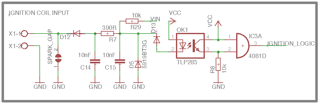
The spark gap is just for the case of a massive (a few kV) spikes. Insulation breakdown or whatever...
D12 is a big diode to keep positive spikes away.
R7 limit the current to the Optocoupler (Value most likely incorrect I designed the coupler led to run off 12v before).
R29 10k Pullup to VIN
D5 Zener to clamp the pullup voltage from VIN to somewhere around 12v. Don't remember the actual value of the zener.
D13 Reverse current protection for the coupler led.
C14 & C15 Just for filtering.
To the right of the coupler is just a AND gate to get a valid logic signal which goes into the micro.
Theory:
X1-1 Is connected to the switched side of the ignition coil.
X1-2 Chassis GND.
X1-1 Will stay at VIN through the coil until the switch closes to GND and thus pulling the signal down.
Optocoupler LED will light up and enable the output transistor pulling the 2nd input of the AND gate to VCC.
Output of AND Gate will go high to VCC.
Ignition coil switches off and X1-1 will turn high again thus turning off the Optocoupler and the output of the AND Gate will turn low.
The circuit is just my theory and it would be much appreciated if someone could take a look at it before I produce the board. It is for personal use and not commercial.
Thanks!
I'm currently designing a control module for a car engine which sits in a boat. Please don't ask why
I need to tap off the pulses on primary (12v) side of the ignition coil. The ignition on that engine is not controlled by any sort of ECU. It is just a mechanical switched transformer with a distributor. Mid 80s tech.
One side of the primary coil goes to +12V and the other side gets switched to GND by a switch on the crankshaft.
Now to the problem: These coils can output massive voltage spikes while disconnecting which would kill any microcontroller input. Resistive dividers are not an option and won't be reliable.
Both the engine and this circuit will share the same GND! Which is important to know while looking at the schematic. VCC = +5v. VIN = +12-14v.
I came up with the following circuit:
The spark gap is just for the case of a massive (a few kV) spikes. Insulation breakdown or whatever...
D12 is a big diode to keep positive spikes away.
R7 limit the current to the Optocoupler (Value most likely incorrect I designed the coupler led to run off 12v before).
R29 10k Pullup to VIN
D5 Zener to clamp the pullup voltage from VIN to somewhere around 12v. Don't remember the actual value of the zener.
D13 Reverse current protection for the coupler led.
C14 & C15 Just for filtering.
To the right of the coupler is just a AND gate to get a valid logic signal which goes into the micro.
Theory:
X1-1 Is connected to the switched side of the ignition coil.
X1-2 Chassis GND.
X1-1 Will stay at VIN through the coil until the switch closes to GND and thus pulling the signal down.
Optocoupler LED will light up and enable the output transistor pulling the 2nd input of the AND gate to VCC.
Output of AND Gate will go high to VCC.
Ignition coil switches off and X1-1 will turn high again thus turning off the Optocoupler and the output of the AND Gate will turn low.
The circuit is just my theory and it would be much appreciated if someone could take a look at it before I produce the board. It is for personal use and not commercial.
Thanks!


Comment