Thank you to the guys at HEGE supporting Badcaps [ HEGE ] [ HEGE DEX Chart ]

Announcement

Collapse
No announcement yet.

Two dead ATX SMPS's - TL494 and FSP3528 based

Collapse
X
 
  • Filter
  • Time
  • Show
Clear All
new posts

    Two dead ATX SMPS's - TL494 and FSP3528 based

    Hello folks, my first post here.

    I have killed 2 SMPS recently. Both of them are totally dead except from 5vSB. No other outputs are working.

    First one:
    FSP ATX-250PA, controlled by FSP3528 & DM 311 for 5vsb, fsp chip is described here: https://www.badcaps.net/forum/showthread.php?t=22171 Killed it by overloading -12V output. I charged a 12V li-on battery pack and i needed more than 12V - i used -12V rail and +3.3V rail. Was going at about 0.2-0.3Amps. Tried -12V + +5V rail as well. Started charging at 4 amps (while my -12V line is rated at 0.5amps) smoked after 4 secs. Stupid me.
    Everything seemed fine inside, no signs of dead components. Found out that Q2 (please refer to generic schematic of HV side of SMPS here: http://www.geocities.ws/luizissao/im...DO_ATX-250.gif ) d304x mosfet was dead/shortened. Strangely no other components were killed, tested every diode and transistor on the circuit. After changing it with FJP13009 () the supply not recover. Only 5vSB was alive.

    After testing the FJP13009 i found out that it got shortened as well, this time just over Base-Emitter junction. It did not make any sound or smoke, had pcb in front of me. After changing FJP mosfet with another one (have ordered 5 ) got the same result. Another brand new FJP mosfet dead. Then I changed both mosfets on primary side - the good d304x as well. I thought it was the reason, as I assumed that they have to be identical. Same result, q2 shortens on Base-emitter. q1 intact. I am soon running out of mosfet's.

    Do you guys have any idea which component might be a reason for this?

    Before the stupid mistake while charging battery it was working fine. I am using it as bench power supply.

    NEXT: Q-TEC PSU ATX 350W LOW NOISE.

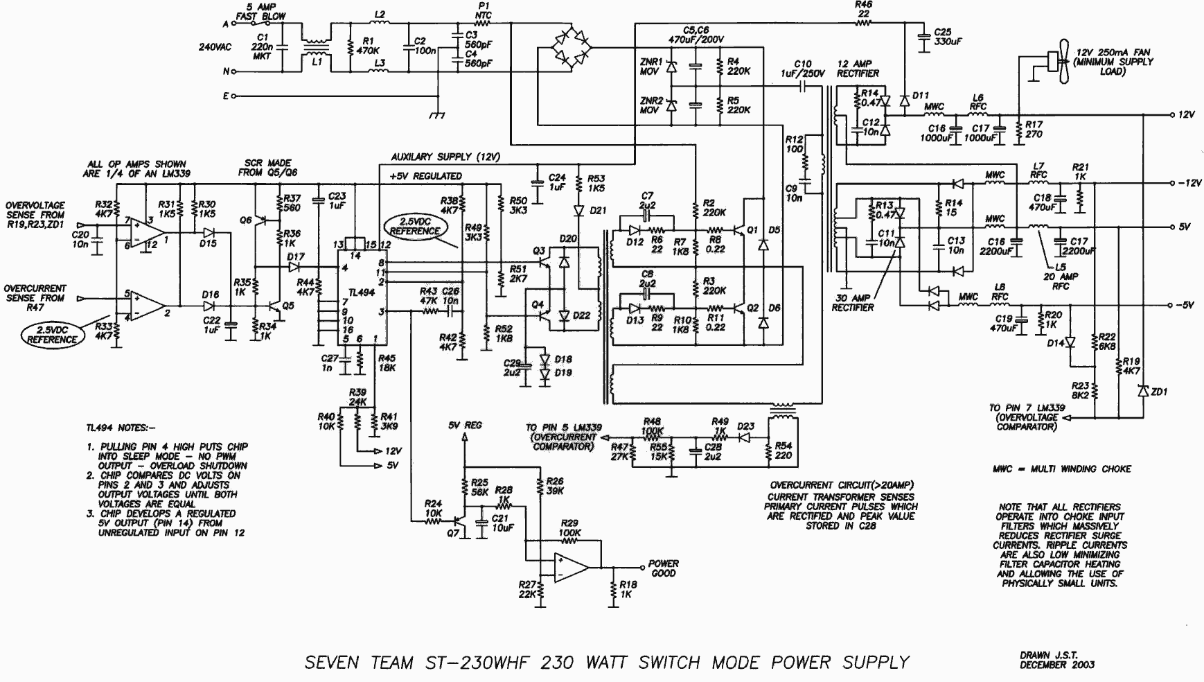
    Used to be a nice atx as it is the only one i have that is controlled by TL494CN (pwm drver) & LM339n (comparator for protections)

    killed it while trying to make an adjustable PS. by this hack: http://boginjr.com/electronics/lv/atx-mod/
    I was nicely adjusting way from ~4-6v (can't remember) (on 12v rail) to 12.00V. It would simply shutdown at 12V, as protections had to be disabled. I had to remove the correct zener diode to eliminate the OV protection but to keep OC protection. I would love to crank this atx up untill 15V (and maybe even more if i decide to change the caps to more than 16V). After removing one diode it would let me go over 12V, but mains fuse exploded at 12.5V.
    After this, the supply never worked again. I have reconnected feedback circuit to original configuration, changed fuse (exploded again), then changed bridge rectifier, both mosfets, 2 resistors under them, thermistor, and 3 diodes - they were black but worked fine - changed them anyway. The mentioned were changed over 3 times trying to turn it on and resulting in main fuse in my apartment switching off every time. Now I have primary side working (no shorts) and 5vSB rail functioning.

    Trying to repair the main output I have changed the transformer for mosfet control, found one open on primary side (had to swap pins on secondary side as it was a little bit different), put a new TL494cn and a replacement LM339n, tested every diode and transistor on the pcb.


    To sum up/applicable to both atx supplies: i test diodes and transistors by simple DMM (diode range), sometimes including a test of desoldered component.
    The reason why I want to bring the 1st supply to life is that it already has nice outputs of voltages, led, switches and so on - it is already converted to easy to use bench top power supply.
    The reason for recovering the second one, the q-tek is that it is the only supply controlled by TL494 chip, therefore can be converted to adjustable supply easily.

    Any ideas of how to continue troubleshooting both power supplies? feeling desperate
    Last edited by domas; 05-02-2013, 06:39 PM.

    #2
    Re: Two dead ATX SMPS's - TL494 and FSP3528 based

    So i have taken some pictures of my supplies. Not sure if this will help you to give me some advise, but it makes the thread more interesting to look at.

    I know my work is a little bit messy. Still learning. How do you guys clean up the black residuals after soldering? I guess it is some soldering paste that stays there. I clean it off mechanically between the tracks on pcb, but is there an easy way to clean the whole pcb off? It looks sooo messy with this crap around the connections where i have soldered.

    The one next to heatsink screw on primary side is getting killed everytime i put a new one in.

    I have attached pictures of FSP supply in this post.
    Attached Files

    Comment


      #3
      Re: Two dead ATX SMPS's - TL494 and FSP3528 based

      And some pictures of Q-tek 350W supply, the one i killed by trying to make an adjustable
      Attached Files

      Comment


        #4
        Re: Two dead ATX SMPS's - TL494 and FSP3528 based

        I think you may want to start with building a current limiting device for the AC side. 40W to 100W incandescent lightbulb in series with the live AC line on the PSU is one easy way to do that. This is how to wire it up:
        https://www.badcaps.net/forum/showpo...4&postcount=70

        Here is what budm's device looks like:
        http://s807.photobucket.com/user/bud...82195675176907

        That way, if something goes wrong when you troubleshoot the PSUs, the light bulb will turn on and stay lit.

        Now as far as the actual problems:
        On the first PSU, check the -12V rectifier diode(s). Mostly likely they became shorted when you pulled 4A of current through them.

        For the Q-tec PSU, check the base-drive circuitry for the BJTs on the primary side. Should be 2 diodes, 2 electrolytic caps (10uF, I believe), and a few resistors.

        Comment


          #5
          Re: Two dead ATX SMPS's - TL494 and FSP3528 based

          Thank you momaka!

          I will consider building a little bit more simple light bulb current limiting device if i will continue to work on shorted primary sides. now both of them are okay there (not shortened at least)

          Regarding the first FSP psu,you were totally right. 2 dioded where shortened. It took me some time to find them as for some reason I was very sure that it should be some heatsinked to-22 design rectifier. Apparently for 0,5amps of current for -12V line it is enough to have 2 simple diodes. And this would kill my transistor.. Funny enough as OC protection should have kicked in, but it did not and would kill the one of primary BJTs. Same way as OC protection would not kick in as i overloaded it for the first time. Strange. Both of my atx do not look too bad - at least they have a lot of components, in comparison to some we all have seen in hall of shame thread.

          Regarding the second supply, the Q-tek, i have been through the mentioned components already. There were 2 resistors that were fried after explosions, as far as I remember 2k7. I couldn't recognize them as the were nicely black, but i have taken them from the same place in another working FSP supply (it was the donating components for 2 killed supplies.) at the same time i have taken primary transistors from it. There were some diodes that were black but still tested to be OK, but i have changed them anyway. Now I am thinking to re-test the caps you mentioned, as I have only a DMM, but I have to read about that a bit. I am also concerned about my transistors... It seems I can't distinguish between BPJ transistor and a mosfet. Have to read some more. Maybe I have put wrong ones in the PS.

          kudos to momaka

          Comment


            #6
            Re: Two dead ATX SMPS's - TL494 and FSP3528 based

            Nice one again, i managed to fix Q-Tec PSU by the way momaka suggested... again Thanks man. There were two 1ohm/1.2ohm (can't remember) resistors cooked to well-done though they did not show signs of heat until i removed them from PCB. They became something like 1.3Mohm and 0.3Mohm I have reinstalled old transformer for mosfet control (identified it as defective, while is was not) and BINGO. Works.

            The problem was that i did not need to remove any zener diodes. It still had the same problem as before, while adjusting from 4.8V to higher value it wuold make and annoying sizzling noise (actually sounded quite extreme) and would be even louder at 12V, and extremely loud over the mentioned voltage. Would still shut down mid 13 volt range, different every time. Later I noticed that if I hold GND cable in my fingers and/or touch the case of ATX the sizzling sound would be way lower and would let me go up to 16V. I understood that ground was missing. I have reinstalled (as i was working with pcb on the table before) the PCB to the case and bingo - it has a little ticking sound at low voltages, but that is normal. I have desoldered output caps for -12, -5, +5 and +3.3 volt rails as they would not be used. Caps voltages had enough headroom but I decided not to put stress on them (all of the rails would adjust together with +12V line accordingly, except for 3.3V rail), i wouldn't use the rails anyway. The supply was still working and adjusting nicely, but i had to keep a little load resistor on 5V rail.

            But I have managed to kill the supply again.

            HOW I have killed it: as my fan is running on 12V rail, the fan would adjust from the output voltage. I wanted it to be controlled by the thermistor as before. There is a low 10-12V output on STBY transormer, i decided to use it. I was checking the voltages on TL494 (Pin 12) where unregulated voltage comes to chip and chip regulates it to 5V on pins 13-14-15. It was working as it should. While testing voltages with my DMM that has thick leads, i have shorted TL494 12pin with 11pin OR the junction of 13-14-15 pins, cant remember. The supply have shut down.

            Current situation: every time i turn on the supply it gives a pulse of voltages to the the rails, ant then shuts down. if I turn it off and turn on again it does not give a pulse again, as I have to discharge 5Vsb trail before turning the PSU on. I have tested every diode on the pcb, and most transistors. I think i will desolder q3 and q4 for proper testing tonight - as now I was just looking for shorts there. Have not tested negative voltages for the turn on pulse, but it seems that every rail is giving a significant voltage on power on, except for 3.3V, as it was 0.03V, but again this might be because of slow DMM I have. Does anybody have an idea where should i look now?

            I do not have a schematic for exact ATX but those two are very close to what I have:


            Thank you in advance..

            P.S. I know my posts are a little bit messy

            Comment


              #7
              Re: Two dead ATX SMPS's - TL494 and FSP3528 based

              solved by replacing diode D12 as for the first schematic.

              Comment


                #8
                Re: Two dead ATX SMPS's - TL494 and FSP3528 based

                Nice work!

                Yeah, the Q-Tek is more or less a standard (or "classic", if you will) half-bridge power supply design so as long as you have some schematics of one of those half-bridge power supplies, it's only a matter of checking components until you find the bad one.

                By the way, here's an interesting voltage mod Th3_uN1Qu3 made to an AT power supply and got very stable results (read post #5):
                https://www.badcaps.net/forum/showthread.php?t=22129

                Originally posted by domas
                How do you guys clean up the black residuals after soldering? I guess it is some soldering paste that stays there.
                Yes, that's just left-over flux. You can clean it with a small piece of rolled paper towel dipped in alcohol. I usually do it with fine tweezers. It's not the fastest method, but it cleans the board very well in my experience.

                Comment


                  #9
                  Re: Two dead ATX SMPS's - TL494 and FSP3528 based

                  I will try the alcohol thingy, thank you.
                  Now some more questions:

                  As my +12V rail is variable, the fan is varying according to voltage. in theory ATX should be undercooled if I set less than 12V on the supply (its hardly spinning at 5V). And it is getting ultra fast at 15.5V (thats the limit I've set)
                  Fan is connected to +12V directly and GND is connected over transistor and thermistor measuring temp of secondary heatsink.

                  I was ok with this speed control system (only i am planning to move thermistor to primary heatsink, as that is only one getting hot at the moment), but variable +12V is too bad for fan. Therefore I decided to connect positive lead of fan to 5vSB transformer. It has two outputs : one is going to to-220 style rectifier (main standby source) and another is going to a diode and is giving 10.21V. That is where I have connected my fan. It has at least 10.21V while main output is at 4.66V to 10.21V which is not too far from 12V. After I crank the supply up to more than 10.21V, voltage at that point is going even higher as there is a diode between the mentioned output and 12V rail. The problem is that fan is getting whole 15.5V at max voltage setting. I might want to put a 12V regulator to avoid overvoltaging the fan. Another issue is that when I turn the atx on but do not turn PS_ON (i have 2 switches) the fan is spinning on standby as well. I might put a mosfet there to control it, as well as I might not do it Not a big deal

                  The question follows:
                  why the f foes the 5vSB transformer have this stange output of 10.21V?? i have traced it to TL494 to 12th pin where it gets unregulated Vcc and it outputs a clean 5V output on 13-14-15 pins. Why the hell there is a need of 2 5V sources on standby (1 main over 3 pin rectifier and another over the chip)? Anybody has an idea? It means that every TL494 based atx has 3 5V outputs: main high current, secondary SB, and another one over the chip? Why the third??

                  As I have attached some pictures of final result it looks a little bit messy because of amount of cables. PS_ON, 2 small load resistors, 3 wires for feedback circuit and so on. There is a protoptyping board with 3 components attached directly to the var. resistor (for feedback adjustments), under all the cables.

                  The green heatsink is where I have put 12V load resistor (remember - fan is loading that rail only over 10.21V setting), before that fan was as a minimal load, and PS wouldn't work without 5V load that was on the pcb. Therefore i heatsinked bot of them (i would hate 5V load resistor overheating), zip tied to heatsink with normal thermal paste (didn't have any glue-based) and superglued (i know, ghetto) to zip ties, as they were not stiff enough. Green heatsink (salvaged from chipset in motherboard) would match the secondary heatsinks cuts - therefore they pressed into each other and i have fastened them with 1 screw in lowest part of green heatsink.

                  Pictures are attached. Hope this is useful for anybody
                  Attached Files

                  Comment


                    #10
                    Re: Two dead ATX SMPS's - TL494 and FSP3528 based

                    Originally posted by domas View Post
                    I will try the alcohol thingy, thank you.
                    Now some more questions:

                    As my +12V rail is variable, the fan is varying according to voltage. in theory ATX should be undercooled if I set less than 12V on the supply (its hardly spinning at 5V). And it is getting ultra fast at 15.5V (thats the limit I've set)
                    Fan is connected to +12V directly and GND is connected over transistor and thermistor measuring temp of secondary heatsink.

                    I was ok with this speed control system (only i am planning to move thermistor to primary heatsink, as that is only one getting hot at the moment), but variable +12V is too bad for fan. Therefore I decided to connect positive lead of fan to 5vSB transformer. It has two outputs : one is going to to-220 style rectifier (main standby source) and another is going to a diode and is giving 10.21V. That is where I have connected my fan. It has at least 10.21V while main output is at 4.66V to 10.21V which is not too far from 12V. After I crank the supply up to more than 10.21V, voltage at that point is going even higher as there is a diode between the mentioned output and 12V rail. The problem is that fan is getting whole 15.5V at max voltage setting. I might want to put a 12V regulator to avoid overvoltaging the fan.

                    Another issue is that when I turn the atx on but do not turn PS_ON (i have 2 switches) the fan is spinning on standby as well. I might put a mosfet there to control it, as well as I might not do it Not a big deal

                    The question follows:
                    why the f foes the 5vSB transformer have this stange output of 10.21V?? i have traced it to TL494 to 12th pin where it gets unregulated Vcc and it outputs a clean 5V output on 13-14-15 pins. Why the hell there is a need of 2 5V sources on standby (1 main over 3 pin rectifier and another over the chip)? Anybody has an idea? It means that every TL494 based atx has 3 5V outputs: main high current, secondary SB, and another one over the chip? Why the third??

                    As I have attached some pictures of final result it looks a little bit messy because of amount of cables. PS_ON, 2 small load resistors, 3 wires for feedback circuit and so on. There is a protoptyping board with 3 components attached directly to the var. resistor (for feedback adjustments), under all the cables.

                    The green heatsink is where I have put 12V load resistor (remember - fan is loading that rail only over 10.21V setting), before that fan was as a minimal load, and PS wouldn't work without 5V load that was on the pcb. Therefore i heatsinked bot of them (i would hate 5V load resistor overheating), zip tied to heatsink with normal thermal paste (didn't have any glue-based) and superglued (i know, ghetto) to zip ties, as they were not stiff enough. Green heatsink (salvaged from chipset in motherboard) would match the secondary heatsinks cuts - therefore they pressed into each other and i have fastened them with 1 screw in lowest part of green heatsink.

                    Pictures are attached. Hope this is useful for anybody
                    You've got the fan tied into the AUX supply for the '494. It will run anytime line voltage is present.

                    Pins 13, 14, and 15 have +5 on them from an internal regulator in the '494. This is also supplied by the AUX voltage.

                    Just tie PS-ON to GND permanently, and use the line switch, if you don't like multiple switches.

                    As for the three supplies: Any ATX PS will have them, not just '494 based ones. You've got +5SB for the motherboard, another one 5-20V for the PWM IC, and related components, opamp if present, and the main 5V output.
                    "pokemon go... to hell!"

                    EOL it...
                    Originally posted by shango066
                    All style and no substance.
                    Originally posted by smashstuff30
                    guilty,guilty,guilty,guilty!
                    guilty of being cheap-made!

                    Comment


                      #11
                      Re: Two dead ATX SMPS's - TL494 and FSP3528 based

                      Yes, the fan is running all the time when the mains cable is plugged and mains swich is turned on, as posted previously. As i said it is not a big deal, but i might want to put a transistor would be activated by PS ON switch.

                      I know that pins 13-14-15 have +5V stabilised by 494, but my fan is 12V I will have to go other way around.

                      Regarding 3 5V supplies: i know their uses, but my question was why have an separate output of 10.21V that is stabilised to 5V anyway? While there is main standy output when line voltage is present as well, at the same time as the strange 10.21V output is active. Couldn't the ICs be supplied directly by 5Vsb line??

                      Comment


                        #12
                        Re: Two dead ATX SMPS's - TL494 and FSP3528 based

                        Originally posted by domas View Post
                        Regarding 3 5V supplies: i know their uses, but my question was why have an separate output of 10.21V that is stabilised to 5V anyway? While there is main standy output when line voltage is present as well, at the same time as the strange 10.21V output is active. Couldn't the ICs be supplied directly by 5Vsb line??
                        I can think of one reason only: isolation. If there was static discharge induced on the 5VSB line, and if the PWM controller is hooked to that line, then this could possibly kill it. Having it's own line that is only available inside the PSU and nowhere else outside makes it isolated from external electrical noise. Also, if the load on the 5VSB produces any kind of ripple, it will not get to the PWM controller, and the PSU will be able to continue to work in a normal manner.

                        Comment


                          #13
                          Re: Two dead ATX SMPS's - TL494 and FSP3528 based

                          Solved fan overvoltaging problem by adding a 12V regulator before the fan.

                          As mentioned before my voltage from Aux supply was 10.21V idle and it was 8.something when fan was running. So now I still have some undercooling in theory; when my atx is set to lower value than 8.6V it spinning at 8.6V anyway, but i crank my atx up to more than that value it is going together with output until 12V, and as I go past this value it still stays the same, 12V.

                          As I did not have 12V regulator with me I was forced to use an adjustable one - LM2576-ADJ. This meant that I had to use a small prototyping board for a regulator, cap, 1 resistor, and one trimmer (to get exact value of voltage needed). I have actually set it to run at 12.30V, just to make sure there is enough air flow. My regulator had one pin for turning it off - this is how I solved another problem of fan spinning on standby without turning PS_ON switch. As I had my switch for grounding PS_on with 3 pins, I was able to connect ps_on cable to switch off pin of regulator when the switch is in OFF position. There is enough voltage in mentioned cable to turn regulator off.

                          A simple question now: https://cdn.badcaps-static.com/pdfs/...c50180d683.pdf suggests that I should use a 1000uF cap on the output. It would be too big size wise there therefore i have put only a 100uF cap. And i haven't put an inductor on output as manual suggests. Again, I am running the regulator at max. 0.15 amp while it is rated at 3amps.. And it works fine. How bad is the idea of using a cap that has 10 times less capacitance and not using the inductor? It is just for running a fan, i do not care about ripple and shit for it.. Should I?

                          That is my funny little prototyping board, and it got wrapped in isolating tape to avoid shorts as you can see in last picture.
                          Attached Files

                          Comment


                            #14
                            Re: Two dead ATX SMPS's - TL494 and FSP3528 based

                            Originally posted by domas View Post
                            Solved fan overvoltaging problem by adding a 12V regulator before the fan.

                            As mentioned before my voltage from Aux supply was 10.21V idle and it was 8.something when fan was running. So now I still have some undercooling in theory; when my atx is set to lower value than 8.6V it spinning at 8.6V anyway, but i crank my atx up to more than that value it is going together with output until 12V, and as I go past this value it still stays the same, 12V.

                            As I did not have 12V regulator with me I was forced to use an adjustable one - LM2576-ADJ. This meant that I had to use a small prototyping board for a regulator, cap, 1 resistor, and one trimmer (to get exact value of voltage needed). I have actually set it to run at 12.30V, just to make sure there is enough air flow. My regulator had one pin for turning it off - this is how I solved another problem of fan spinning on standby without turning PS_ON switch. As I had my switch for grounding PS_on with 3 pins, I was able to connect ps_on cable to switch off pin of regulator when the switch is in OFF position. There is enough voltage in mentioned cable to turn regulator off.

                            A simple question now: https://cdn.badcaps-static.com/pdfs/...c50180d683.pdf suggests that I should use a 1000uF cap on the output. It would be too big size wise there therefore i have put only a 100uF cap. And i haven't put an inductor on output as manual suggests. Again, I am running the regulator at max. 0.15 amp while it is rated at 3amps.. And it works fine. How bad is the idea of using a cap that has 10 times less capacitance and not using the inductor? It is just for running a fan, i do not care about ripple and shit for it.. Should I?

                            That is my funny little prototyping board, and it got wrapped in isolating tape to avoid shorts as you can see in last picture.
                            I am amazed that regulator works partially, it is a switching regulator, it NEEDS the inductor to function as intended. I'm surprised that capacitor hasn't blown up due to the ripple current on that - especially without the inductor!
                            Muh-soggy-knee

                            Comment


                              #15
                              Re: Two dead ATX SMPS's - TL494 and FSP3528 based

                              Originally posted by ben7 View Post
                              I am amazed that regulator works partially, it is a switching regulator, it NEEDS the inductor to function as intended. I'm surprised that capacitor hasn't blown up due to the ripple current on that - especially without the inductor!
                              Nice answer I haven't actually stress-tested the regulator yet, just checked it for few minutes

                              Okay, it seems like I have to redo my voltage control )

                              Now I would like to ask the following:
                              a) Which ripple you are referring to? Is it the one caused by ATX power supply or the one that is actually made by the regulator?
                              b) If I was using a linear regulator, this ripple filters would not be needed?
                              c) Can you guys help me finding a correct inductor? Manual suggests 100uH. Never worked with the before. I can see some of them are very resistor-like http://www.taydaelectronics.com/100uh-inductor.html How are they typically marked on the PCB's? I mean like resistors are marked as R1, R5, caps are C2, C3 etc. Or should my inductor be a coil-based one?
                              d) Do I have to use 1000uF cap as manual suggests? As mentioned I am only using 5% of the regulators max current capacity.

                              Comment


                                #16
                                Re: Two dead ATX SMPS's - TL494 and FSP3528 based

                                added an inductor, increased the cap to 220uF

                                Answers to my questions:
                                a) It was ripple created by regulator. After regulator mod my atx started making weird noise at 14,5V-15,5V. After improving my regulator mod, now it is silent there.. there is a bit of buzzing sound on lowest voltage setting, but it was always there as it is normal with adjustable atx supplies.
                                b) still not sure 100%, but i understand they wouldn't be needed with linear
                                c) it is easy, same color markings as for resistors, and they are marked as L
                                d) Now using 220uF, not 100uF anymore. Hopefully this will be enough

                                I haven't heatsinked the regulator, it runs just warm, maybe about 45 deg. celsius, which is much cooler that load resistors. My regulator is salvaged from some board so it is in DDPAK/TO-263 package, this would make it tricky to sink. Will see how this works.

                                Comment


                                  #17
                                  Re: Two dead ATX SMPS's - TL494 and FSP3528 based

                                  ok, bump an old thread..

                                  Q-tec is fine and alive.. PS has received a voltmeter+ammeter combination from dealextreme quite some time ago, it has an ability to sense up to 50amps
                                  http://dx.com/p/mini-digital-blue-re...e-shunt-219592
                                  due to being a cheapo meter it does not show any current before it is more than 0.5a for some reason. But that was a cheapo project so it will be just fine.

                                  The fsp bastard is annoying me for is inability to regulate.. I guess i need to put more load on 5V rail. I have done some testing, and it seems that either the crappy p/s is just too stupid and you have to load the two rails by the same load or it has its problems (full of teapo caps, non of them seem to have any external damage though).. This p/s is for testing things only, nothing vital, so no i will not recap it before it is actually dead or semi-dead. It seems that there is no load resistor on 12V rail.

                                  There is one on 5V rail and i can't access it at the moment as it is pita to remove the board after my modification. Same with caps. That is why i will only remove the board when i really need to. And resistor is hearshrinked so i cant see the value. I do not care too much about 5V rails regulation as i use 12Vrail the most, and sometimes it goes to less than 11V!!!

                                  I have few favorite load resistors around: 96ohm which if connected to 5V rail does increase 12V rail with 0.2V, which is not enough. And I have two power resistors of 1.8ohm for bad ass testing )

                                  If i measure the resistance of GND TO 5V it is 42 ohms. Probably most of it is a load resistor.

                                  12V measures to 322ohms and that is probably intereferring with the fan. I still do not care about this one as i will load it when i use it.

                                  Specs without any addition loads (fan spinning at barely 4volts, and original 5v resistor intact):
                                  5V: 5.08V
                                  12v: 11.88V
                                  ---
                                  Loading 5V with 96ohm resistor
                                  12V: 11.94V
                                  5V: 5.06V
                                  --
                                  Loading 12V with 1.8ohm resistor, should be about 6 amps:
                                  5V: 5.38V
                                  12V: 10.8V
                                  ---
                                  Loading 12V with 1.8ohms / circa 6amps and 5V with 96ohm
                                  12V: 10.92V
                                  5V: 5.33V
                                  ---
                                  now the bad ass testing
                                  Loading each rail with 1.8ohm resistors, so ~6a and ~2.4a each
                                  5V: 5.07V
                                  12V: 11.81V
                                  --
                                  After the last experiment, you can see that if i want to use 12V rail with loads up to 6amps whth tolerances of 0.2V i should constantly load 5V rail with 2.4A not gonna happen.

                                  Is this behavior normal with cheap p/s (i know it is low end device with cheap components) but they did not skip many of them or i should check caps of some 12V rail?

                                  thank you

                                  Comment


                                    #18
                                    Re: Two dead ATX SMPS's - TL494 and FSP3528 based

                                    Originally posted by domas View Post
                                    Is this behavior normal with cheap p/s
                                    Usually no. Most cheap PSUs will tolerate a lot more cross-loading than this. It's probably just a crappy design/platform. Older half-bridge Sirtec PSUs, for example, have/had the same problem; load them on the 5V and they are happy, load them on the 12V heavily and they oscillate.

                                    Deer PSUs, on the other hand, no matter how crappy, always tend to regulate wonderfully. Also, low-end ISO PSUs from Channel Well have great regulation too, even though most of them barely have enough components to function. I have a totally gutless ISO PSU that I can load the 12V rail with 2 to 3 amps, and it is still in spec voltage-wise (not sure about ripple, though... do you think a single 680uF cap can do much there ).

                                    Originally posted by domas View Post
                                    or i should check caps of some 12V rail?
                                    Well, if the caps are bad, that could cause the lower voltage and sloppy regulation too.
                                    But from what I remember reading long time ago, FSP PSUs just aren't good with regulation. Someone please correct me if I am wrong here, though.

                                    Comment


                                      #19
                                      Re: Two dead ATX SMPS's - TL494 and FSP3528 based

                                      i am not an expert in different topologies and regulation methods

                                      But it would be interesting to see how to improve that. It is just that FSP chips lack documentation. Is this p/s generally considered worthless POS?

                                      Comment


                                        #20
                                        Re: Two dead ATX SMPS's - TL494 and FSP3528 based

                                        Hello domas could u give me the spec of two transistor Q1,Q2 at the psu FSP ATX-250PA.

                                        Comment

                                        Working...
                                        X