Thank you to the guys at HEGE supporting Badcaps [ HEGE ] [ HEGE DEX Chart ]

Announcement

Collapse
No announcement yet.

Controlling these bad boys

Collapse
X
 
  • Filter
  • Time
  • Show
Clear All
new posts

    Controlling these bad boys

    OK, so for a mod project i plan on doing in the near future, I have a few fans from Hell (erm, sorry, I meant Dell), more specifically, Delta AFC0912DE fans. Unfortunately, a circuit like the one in https://www.badcaps.net/forum/showthread.php?t=18774 ain't gonna work, for two reasons: 1. I want to run 4 of these fans off each controller, and they draw 2.5A each and 2. They won't try to spin below about 9 or 10v.

    So, it seems that using the PWM wire is the way to go. I was thinking about using a circuit like this (from PCBHeaven):


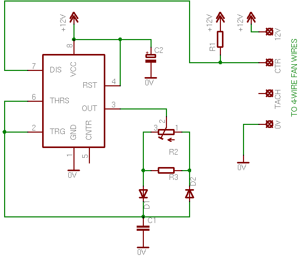
    It looks good except for 1 thing - I want to use slider pots, which are only available in 10K here, and the pot used here as a 1K. So, my question is, is there an easy way of modifying this circuit to use a 10K pot? Or could you lower the value of R3?

    EDIT: Parts list:

    R1: Resistor 1 KOhm 1/4 Watt 5% Carbon Film
    R2: 1 KOhm potentiometer
    R3: Resistor 4.7 KOhm 1/4 Watt 5% Carbon Film

    C1: 0.1 uF ceramic capacitor
    C2: 1 uF 16 Volts electrolytic capacitor

    IC1: 555 Timer

    D1 and D2: 1N4148 Switching Diode
    Last edited by c_hegge; 03-16-2012, 01:21 AM.
    I love putting bad caps and flat batteries in fire and watching them explode!!

    No wonder it doesn't work! You installed the jumper wires backwards

    Main PC: Core i7 3770K 3.5GHz, Gigabyte GA-Z77M-D3H-MVP, 8GB Kingston HyperX DDR3 1600, 240GB Intel 335 Series SSD, 750GB WD HDD, Sony Optiarc DVD RW, Palit nVidia GTX660 Ti, CoolerMaster N200 Case, Delta DPS-600MB 600W PSU, Hauppauge TV Tuner, Windows 7 Home Premium

    Office PC: HP ProLiant ML150 G3, 2x Xeon E5335 2GHz, 4GB DDR2 RAM, 120GB Intel 530 SSD, 2x 250GB HDD, 2x 450GB 15K SAS HDD in RAID 1, 1x 2TB HDD, nVidia 8400GS, Delta DPS-650BB 650W PSU, Windows 7 Pro

    #2
    Re: Controlling these bad boys

    Are you building these as individual control separate for each fan or all the fans going into one case and want to control from centralized location?

    10k ohm pots should be ok.

    Here's one I did for PS3 fan mod, which uses a 100k pot and 555 chip.

    I "saved" the site for future reference because the guy sold off his kits/design to some third party. But I think it might help you, so I've upload it to my personal web server here at home.
    http://madprofessor.zapto.org/ps3fanmod/ps3fanmod.htm

    If you still want to use the arduino design to control all of them at the same time, you can modify my design.

    Wire the 12v and gnd directly to supply then depending on PWM max voltage; it should be easy to obtain, just measure the voltage on the pwm signal wire. If it is 5v or 3.3v, You could wire PWM signal wire directly to atmega8/16/328 chip. According to arduino, they can put out 5v supposedly. Add a resistor to counter voltage to spec. Or simply add a voltage regulator to provide the pwm supply and some tip120 or similar transistor to handle the rest.

    I think it would work instead of gnd to gnd connection, it'll be just hot to hot.

    Comment


      #3
      Re: Controlling these bad boys

      the fans will all be going into the same case and I want to control them all from the one controller. If 10K sliders will work with the circuit in my first post then I'll go with that.
      I love putting bad caps and flat batteries in fire and watching them explode!!

      No wonder it doesn't work! You installed the jumper wires backwards

      Main PC: Core i7 3770K 3.5GHz, Gigabyte GA-Z77M-D3H-MVP, 8GB Kingston HyperX DDR3 1600, 240GB Intel 335 Series SSD, 750GB WD HDD, Sony Optiarc DVD RW, Palit nVidia GTX660 Ti, CoolerMaster N200 Case, Delta DPS-600MB 600W PSU, Hauppauge TV Tuner, Windows 7 Home Premium

      Office PC: HP ProLiant ML150 G3, 2x Xeon E5335 2GHz, 4GB DDR2 RAM, 120GB Intel 530 SSD, 2x 250GB HDD, 2x 450GB 15K SAS HDD in RAID 1, 1x 2TB HDD, nVidia 8400GS, Delta DPS-650BB 650W PSU, Windows 7 Pro

      Comment


        #4
        Re: Controlling these bad boys

        Since R2, R3, and C1 are part of the timing circuits, if you want to keep the same timing of the PWM range of the adjustment of the original design, then if you increase the R by the factor of 10 then C should be decrease by a factor of 10, the pot should also be linear type not audio taper type.
        Never stop learning
        Basic LCD TV and Monitor troubleshooting guides.
        http://www.badcaps.net/forum/showthr...956#post305956

        Voltage Regulator (LDO) testing:
        http://www.badcaps.net/forum/showthr...999#post300999

        Inverter testing using old CFL:
        http://www.badcaps.net/forum/showthr...er+testing+cfl

        Tear down pictures : Hit the ">" Show Albums and stories" on the left side
        http://s807.photobucket.com/user/budm/library/

        TV Factory reset codes listing:
        http://www.badcaps.net/forum/showthread.php?t=24809

        Comment


          #5
          Re: Controlling these bad boys

          Here is my 555 timer PWM circuit post apocalyptic mosfet meltdown (from leaving the gate floating unattended while taking a shower... it was fine while I was tinkering with it for several minutes but apparently it decided to switch itself on sometime during the rinse cycle)... using an irf640a mosfet normally the heatsink doesn't even get warm during operation.


          I'm using a SEPIC topology on the output (yeah there is an error on the wiring of the output side, after meltdown I moved some stuff). This gives me a completly adjustable non-inverted output voltage of between 0-20V+ simply by varying the duty cycle.

          I still have a bunch of refinements and add-ons I would like to include...

          1. Switch 555 timer #1 to 556 timer.
          2. Connect a 10k resistor between pin 8 and pin 4 of 556 timer #1, and put an NPN transistor between pin 4 and ground. That way I can perhaps use a zener diode to detect overvoltage conditions caused by fan failure or cranking up the duty cycle too high... when the base of the transistor opens up it should pull pin 4 down low effectively acting as a crowbar requiring a button press to turn the circuit back on.
          3. Rig up 556 timer #2 as an astable multivibrator driving a speaker to act as a fault alarm. Might use a PNP transistor somewhere along the lines so that when the output of timer #1 goes low it kicks on with a side by side NPN to warn when the output voltage is near maximum.
          4. Configure the main PWM timer as to allow for non-proportional independant setting of space and mark time. I'm shooting for a switching frequency of around 30Khz and trying to minimize the ripple current going thru the coupling and output filter capacitors. Might even tinker with doing some sort of low-pass inductor.
          5. Wind a center tapped toroid inductor, optimize inductance, capacitor, resistor values to optimize efficiency. Play with various mosfets and research the need for gate/pulldown resistors.
          6. Maybe incorporate a dual or quad voltage comparator in lieu of zener diodes.
          7. Add on as many jumper wires and or/components on one single breadboard to make things as complicated and/or cramped together as I possibly can.
          8. Incorporate a NTC or PTC thermistor in such a way that I can set my output voltage and have the slope/ramp/gain on the output increase proportionately, this will also serve as an over temperature alarm due to the output voltage going too high trying to compensate.
          9. Say fuck it all, rig up a MC34063 switching an external FET as a boost converter (yes it can be done) to achieve an output voltage of around 16v and then use some other means to decrease the voltage to a level that suits my fancy.
          Attached Files

          Comment


            #6
            Re: Controlling these bad boys

            Originally posted by budm View Post
            Since R2, R3, and C1 are part of the timing circuits, if you want to keep the same timing of the PWM range of the adjustment of the original design, then if you increase the R by the factor of 10 then C should be decrease by a factor of 10, the pot should also be linear type not audio taper type.
            Noted.

            So basically, it will work fine with a 10K pot If I use a 0.01uF cap for C1? If so, then that will be easy.
            I love putting bad caps and flat batteries in fire and watching them explode!!

            No wonder it doesn't work! You installed the jumper wires backwards

            Main PC: Core i7 3770K 3.5GHz, Gigabyte GA-Z77M-D3H-MVP, 8GB Kingston HyperX DDR3 1600, 240GB Intel 335 Series SSD, 750GB WD HDD, Sony Optiarc DVD RW, Palit nVidia GTX660 Ti, CoolerMaster N200 Case, Delta DPS-600MB 600W PSU, Hauppauge TV Tuner, Windows 7 Home Premium

            Office PC: HP ProLiant ML150 G3, 2x Xeon E5335 2GHz, 4GB DDR2 RAM, 120GB Intel 530 SSD, 2x 250GB HDD, 2x 450GB 15K SAS HDD in RAID 1, 1x 2TB HDD, nVidia 8400GS, Delta DPS-650BB 650W PSU, Windows 7 Pro

            Comment


              #7
              Re: Controlling these bad boys

              Originally posted by c_hegge View Post
              So, it seems that using the PWM wire is the way to go. I was thinking about using a circuit like this (from PCBHeaven):
              Should work fine. I used the same circuit to make a controller for the PS3's PWM fan. Worked great for me. The switching frequency of your PWM circuit will be given by:
              f = 1.44 / (R2 * C1)
              Where f is the frequency (in Hz), R2 is in Ohms, and C1 is in Farads (uF is 10^-6).
              With the parts in your parts list (C1 = 0.1uF and R2 = 1 KOhm), f = 14.4 KHz.
              For the PS3 fan, I used 5K pot and 0.1uF capacitor (so f = 2880 Hz).

              Comment


                #8
                Re: Controlling these bad boys

                huh? 1.44/(1000 x 0.1) = 0.0144Hz, not 14.4KHz
                I love putting bad caps and flat batteries in fire and watching them explode!!

                No wonder it doesn't work! You installed the jumper wires backwards

                Main PC: Core i7 3770K 3.5GHz, Gigabyte GA-Z77M-D3H-MVP, 8GB Kingston HyperX DDR3 1600, 240GB Intel 335 Series SSD, 750GB WD HDD, Sony Optiarc DVD RW, Palit nVidia GTX660 Ti, CoolerMaster N200 Case, Delta DPS-600MB 600W PSU, Hauppauge TV Tuner, Windows 7 Home Premium

                Office PC: HP ProLiant ML150 G3, 2x Xeon E5335 2GHz, 4GB DDR2 RAM, 120GB Intel 530 SSD, 2x 250GB HDD, 2x 450GB 15K SAS HDD in RAID 1, 1x 2TB HDD, nVidia 8400GS, Delta DPS-650BB 650W PSU, Windows 7 Pro

                Comment


                  #9
                  Re: Controlling these bad boys

                  Originally posted by c_hegge View Post
                  huh? 1.44/(1000 x 0.1) = 0.0144Hz, not 14.4KHz
                  That's because you missed a piece. For the calculation to work the units must be in the base(?) value, therefore Hertz, Ohms, and Farads. (no prefix)

                  C1 is 0.1 microfarad, not 0.1 farad!

                  Your calculation should be: 1.44 Hz /(1000 Ohms x 0.0000001 Farad) = 14400 Hz (14.4 kHz)
                  "Tantalum for the brave, Solid Aluminium for the wise, Wet Electrolytic for the adventurous"
                  -David VanHorn

                  Comment


                    #10
                    Re: Controlling these bad boys

                    of course
                    I love putting bad caps and flat batteries in fire and watching them explode!!

                    No wonder it doesn't work! You installed the jumper wires backwards

                    Main PC: Core i7 3770K 3.5GHz, Gigabyte GA-Z77M-D3H-MVP, 8GB Kingston HyperX DDR3 1600, 240GB Intel 335 Series SSD, 750GB WD HDD, Sony Optiarc DVD RW, Palit nVidia GTX660 Ti, CoolerMaster N200 Case, Delta DPS-600MB 600W PSU, Hauppauge TV Tuner, Windows 7 Home Premium

                    Office PC: HP ProLiant ML150 G3, 2x Xeon E5335 2GHz, 4GB DDR2 RAM, 120GB Intel 530 SSD, 2x 250GB HDD, 2x 450GB 15K SAS HDD in RAID 1, 1x 2TB HDD, nVidia 8400GS, Delta DPS-650BB 650W PSU, Windows 7 Pro

                    Comment


                      #11
                      Re: Controlling these bad boys

                      I built the circuit in my first post, with the higher value Pot and the lower value cap. It works, but one thing that I don't particularly like is that the 'idle speed' is a bit high. When you connect the fan's PWM wire to Ground, it's almost silent. On this controller, though, it's still a bit loud, even with the pot on low. Is there any way of tweaking the idle speed? Or does the ground wire trick make the fan go slower than any PWM signal can make it go?
                      I love putting bad caps and flat batteries in fire and watching them explode!!

                      No wonder it doesn't work! You installed the jumper wires backwards

                      Main PC: Core i7 3770K 3.5GHz, Gigabyte GA-Z77M-D3H-MVP, 8GB Kingston HyperX DDR3 1600, 240GB Intel 335 Series SSD, 750GB WD HDD, Sony Optiarc DVD RW, Palit nVidia GTX660 Ti, CoolerMaster N200 Case, Delta DPS-600MB 600W PSU, Hauppauge TV Tuner, Windows 7 Home Premium

                      Office PC: HP ProLiant ML150 G3, 2x Xeon E5335 2GHz, 4GB DDR2 RAM, 120GB Intel 530 SSD, 2x 250GB HDD, 2x 450GB 15K SAS HDD in RAID 1, 1x 2TB HDD, nVidia 8400GS, Delta DPS-650BB 650W PSU, Windows 7 Pro

                      Comment


                        #12
                        Re: Controlling these bad boys

                        May be because the PWM frequency is now too low from the original design for this fan.
                        Never stop learning
                        Basic LCD TV and Monitor troubleshooting guides.
                        http://www.badcaps.net/forum/showthr...956#post305956

                        Voltage Regulator (LDO) testing:
                        http://www.badcaps.net/forum/showthr...999#post300999

                        Inverter testing using old CFL:
                        http://www.badcaps.net/forum/showthr...er+testing+cfl

                        Tear down pictures : Hit the ">" Show Albums and stories" on the left side
                        http://s807.photobucket.com/user/budm/library/

                        TV Factory reset codes listing:
                        http://www.badcaps.net/forum/showthread.php?t=24809

                        Comment


                          #13
                          Re: Controlling these bad boys

                          I did try a higher value for C1 (0.02uF as opposed to 0.01uF), which increases the frequency. It didn't change the speed at all.
                          I love putting bad caps and flat batteries in fire and watching them explode!!

                          No wonder it doesn't work! You installed the jumper wires backwards

                          Main PC: Core i7 3770K 3.5GHz, Gigabyte GA-Z77M-D3H-MVP, 8GB Kingston HyperX DDR3 1600, 240GB Intel 335 Series SSD, 750GB WD HDD, Sony Optiarc DVD RW, Palit nVidia GTX660 Ti, CoolerMaster N200 Case, Delta DPS-600MB 600W PSU, Hauppauge TV Tuner, Windows 7 Home Premium

                          Office PC: HP ProLiant ML150 G3, 2x Xeon E5335 2GHz, 4GB DDR2 RAM, 120GB Intel 530 SSD, 2x 250GB HDD, 2x 450GB 15K SAS HDD in RAID 1, 1x 2TB HDD, nVidia 8400GS, Delta DPS-650BB 650W PSU, Windows 7 Pro

                          Comment


                            #14
                            Re: Controlling these bad boys

                            You increased thr R2 value of the pot by factor of 10, then the value of the cap will have to go down by the factor of 10, original design was 0.1uf.
                            R3 also need to go up to 47k.
                            Higher value cap = lower frequency.
                            http://www.bowdenshobbycircuits.info/555.htm
                            Last edited by budm; 03-23-2012, 04:47 PM.
                            Never stop learning
                            Basic LCD TV and Monitor troubleshooting guides.
                            http://www.badcaps.net/forum/showthr...956#post305956

                            Voltage Regulator (LDO) testing:
                            http://www.badcaps.net/forum/showthr...999#post300999

                            Inverter testing using old CFL:
                            http://www.badcaps.net/forum/showthr...er+testing+cfl

                            Tear down pictures : Hit the ">" Show Albums and stories" on the left side
                            http://s807.photobucket.com/user/budm/library/

                            TV Factory reset codes listing:
                            http://www.badcaps.net/forum/showthread.php?t=24809

                            Comment


                              #15
                              Re: Controlling these bad boys

                              Ah. thanks for the link.

                              The PWM target frequency is 25KHz, with between 21 and 28 being acceptable.

                              With my current parts, I'm only getting 7.4KHz, so it's a wonder it works at all. However, according to that calculator, I can use a 3.3nF (.0033uF) cap with my current parts and that will get about 22.5KHz, which is within tolerance, so I'll try that.
                              I love putting bad caps and flat batteries in fire and watching them explode!!

                              No wonder it doesn't work! You installed the jumper wires backwards

                              Main PC: Core i7 3770K 3.5GHz, Gigabyte GA-Z77M-D3H-MVP, 8GB Kingston HyperX DDR3 1600, 240GB Intel 335 Series SSD, 750GB WD HDD, Sony Optiarc DVD RW, Palit nVidia GTX660 Ti, CoolerMaster N200 Case, Delta DPS-600MB 600W PSU, Hauppauge TV Tuner, Windows 7 Home Premium

                              Office PC: HP ProLiant ML150 G3, 2x Xeon E5335 2GHz, 4GB DDR2 RAM, 120GB Intel 530 SSD, 2x 250GB HDD, 2x 450GB 15K SAS HDD in RAID 1, 1x 2TB HDD, nVidia 8400GS, Delta DPS-650BB 650W PSU, Windows 7 Pro

                              Comment


                                #16
                                Re: Controlling these bad boys

                                With the 3.3nF cap, the idle speed is no different. However, with the 10nF cap, some fans would make a high pitched whine when at low speeds, which seems to have disappeared now, so I think the frequency is now about right. I guess that's just what you get for using server fans. I'm not too concerned about the idle speed issue, though. I think I'll just add an 'idle' switch to select whither the PWM wire goes to Ground or the controller.
                                I love putting bad caps and flat batteries in fire and watching them explode!!

                                No wonder it doesn't work! You installed the jumper wires backwards

                                Main PC: Core i7 3770K 3.5GHz, Gigabyte GA-Z77M-D3H-MVP, 8GB Kingston HyperX DDR3 1600, 240GB Intel 335 Series SSD, 750GB WD HDD, Sony Optiarc DVD RW, Palit nVidia GTX660 Ti, CoolerMaster N200 Case, Delta DPS-600MB 600W PSU, Hauppauge TV Tuner, Windows 7 Home Premium

                                Office PC: HP ProLiant ML150 G3, 2x Xeon E5335 2GHz, 4GB DDR2 RAM, 120GB Intel 530 SSD, 2x 250GB HDD, 2x 450GB 15K SAS HDD in RAID 1, 1x 2TB HDD, nVidia 8400GS, Delta DPS-650BB 650W PSU, Windows 7 Pro

                                Comment


                                  #17
                                  Re: Controlling these bad boys

                                  Not all the fans have the same control circuits inside for the speed control, so you will have to experiment with the circuits to make it work with your fan.
                                  Never stop learning
                                  Basic LCD TV and Monitor troubleshooting guides.
                                  http://www.badcaps.net/forum/showthr...956#post305956

                                  Voltage Regulator (LDO) testing:
                                  http://www.badcaps.net/forum/showthr...999#post300999

                                  Inverter testing using old CFL:
                                  http://www.badcaps.net/forum/showthr...er+testing+cfl

                                  Tear down pictures : Hit the ">" Show Albums and stories" on the left side
                                  http://s807.photobucket.com/user/budm/library/

                                  TV Factory reset codes listing:
                                  http://www.badcaps.net/forum/showthread.php?t=24809

                                  Comment


                                    #18
                                    Re: Controlling these bad boys

                                    Originally posted by c_hegge View Post
                                    I built the circuit in my first post, with the higher value Pot and the lower value cap. It works, but one thing that I don't particularly like is that the 'idle speed' is a bit high. When you connect the fan's PWM wire to Ground, it's almost silent. On this controller, though, it's still a bit loud, even with the pot on low. Is there any way of tweaking the idle speed? Or does the ground wire trick make the fan go slower than any PWM signal can make it go?
                                    I'm guessing the problem is that the PWM duty cycle from your circuit doesn't go all the way down to 0, thus it can't fully emulate the situation when you have it connected to ground.

                                    As I posted in another thread, have a look at this controller: http://web.archive.org/web/200704231.../circuit3.html

                                    It does a full 0 - 100% duty cycle. Since it's designed for non-PWM fans you will need to modify it, I expect remove the MOSFET and replace the PWM control wire in it's place at the gate connection.

                                    (Note, it only works with 12v supply)
                                    "Tantalum for the brave, Solid Aluminium for the wise, Wet Electrolytic for the adventurous"
                                    -David VanHorn

                                    Comment


                                      #19
                                      Re: Controlling these bad boys

                                      Originally posted by c_hegge View Post
                                      Unfortunately, a circuit like the one in https://www.badcaps.net/forum/showthread.php?t=18774 ain't gonna work, for two reasons: 1. I want to run 4 of these fans off each controller, and they draw 2.5A each and 2. They won't try to spin below about 9 or 10v.
                                      You could use that controller to drive the PWM wire on the fans. You wouldn't need the big power transistors on the output of that controller.

                                      I don't think a 555 timer by itself can provide a full 0-100% duty cycle. You would need extra components, just like the circuit in the above post.

                                      Comment

                                      Working...
                                      X