Announcement

Collapse
No announcement yet.

Acer x193w with Darfon B092-XXX inverter - assistance needed! [lotsa pics!]

Collapse
X
 
  • Filter
  • Time
  • Show
Clear All
new posts

    #21
    Re: Acer x193w with Darfon B092-XXX inverter - assistance needed! [lotsa pics!]

    Originally posted by retiredcaps View Post
    Just take your time and be careful not to short something out by rushing through things. I always use the power bar with nothing else on it and plugged into an single outlet.
    I followed your advice closely - also once turning the power off I clicked the power button on the monitor a few times to help discharge the caps.

    I used insulated pliers to switch the connectors around.

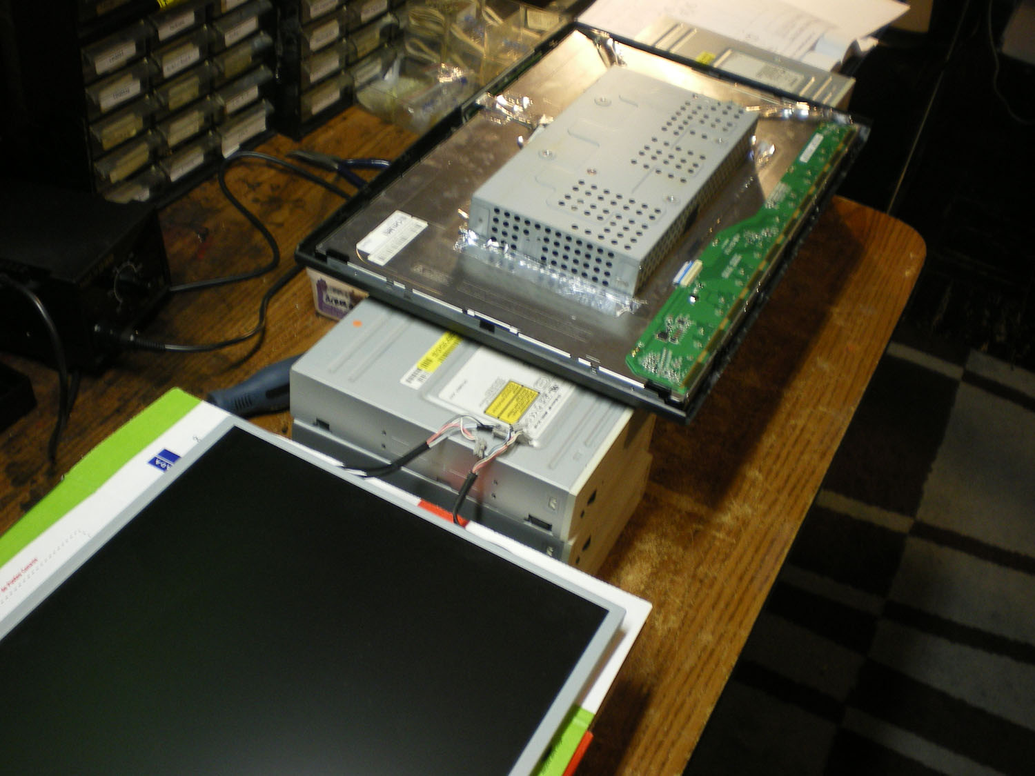
    I had to come up with a way of seeing the bottom of the screen without disturbing the setup...I knew that pile of CD roms I have would come in handy some day! haha


    Unfortunately, the monitor still does it, having tried replacing each CCFL with a working one.
    Attached Files

    Comment


      #22
      Re: Acer x193w with Darfon B092-XXX inverter - assistance needed! [lotsa pics!]

      Oops, I forgot to add - there is most definitely a buzzing sound coming from the inverter when it's trying to power the CCFL's. The buzzing stops when the CCFL's go out.

      Comment


        #23
        Re: Acer x193w with Darfon B092-XXX inverter - assistance needed! [lotsa pics!]

        Originally posted by HexInverter View Post
        Oops, I forgot to add - there is most definitely a buzzing sound coming from the inverter when it's trying to power the CCFL's. The buzzing stops when the CCFL's go out.
        Okay, let's recap what we have done so far.

        1) All caps except the 22uF 50V have been replaced with Panasonic.

        2) CCFL have been tested with another monitor and they seem okay.

        3) Transformer secondaries measure 839/840 which indicates good.

        4) The SMD FET P2804 tests good (no short).

        5) Fuse F301 tests good.

        Questions.

        1) Do you have a ring tester? The ohms test on the secondary doesn't test for shorted turns. If not, don't worry too much about it.

        3) The SMD FET tab looks a bit dodgy with that blob of solder? Is that condition how you originally found it?

        Next Step.

        The next step is probably to monitor BIT3715. I'm now moving into relatively inexperienced terriority because I haven't done one of these firsthand. So PlainBill will have to lend a helping hand here. The datasheet is at

        https://cdn.badcaps-static.com/pdfs/...e40530e824.pdf

        Basically what PlainBill will probably ask you do is measure voltages of that BIT3715 and monitor the feedback or sense circuitry. These are the signals which tell the BIT3715 to enable/disable the backlight. He may also ask for tighter pictures of that BIT3715 area with a top down view (no flash, macro mode on, - take picture next to window on a sunny day).
        --- begin sig file ---

        If you are new to this forum, we can help a lot more if you please post clear focused pictures (max resolution 2000x2000 and 2MB) of your boards using the manage attachments button so they are hosted here. Information and picture clarity compositions should look like this post.

        We respectfully ask that you make some time and effort to read some of the guides available for basic troubleshooting. After you have read through them, then ask clarification questions or report your findings.

        Please do not post inline and offsite as they slow down the loading of pages.

        --- end sig file ---

        Comment


          #24
          Re: Acer x193w with Darfon B092-XXX inverter - assistance needed! [lotsa pics!]

          Originally posted by retiredcaps View Post
          Okay, let's recap what we have done so far.

          1) All caps except the 22uF 50V have been replaced with Panasonic.

          2) CCFL have been tested with another monitor and they seem okay.

          3) Transformer secondaries measure 839/840 which indicates good.

          4) The SMD FET P2804 tests good (no short).

          5) Fuse F301 tests good.

          Questions.

          1) Do you have a ring tester? The ohms test on the secondary doesn't test for shorted turns. If not, don't worry too much about it.

          3) The SMD FET tab looks a bit dodgy with that blob of solder? Is that condition how you originally found it?

          Next Step.

          The next step is probably to monitor BIT3715. I'm now moving into relatively inexperienced terriority because I haven't done one of these firsthand. So PlainBill will have to lend a helping hand here. The datasheet is at

          https://cdn.badcaps-static.com/pdfs/...e40530e824.pdf

          Basically what PlainBill will probably ask you do is measure voltages of that BIT3715 and monitor the feedback or sense circuitry. These are the signals which tell the BIT3715 to enable/disable the backlight. He may also ask for tighter pictures of that BIT3715 area with a top down view (no flash, macro mode on, - take picture next to window on a sunny day).
          Nope, no ring tester

          Yup, that's how the SMD tab was. I will check and resolder that joint. I'm going to have to be really careful not to toast the FET when removing solder though!

          My camera battery just died...argh. I always forget it plugged in on data transfer mode to my PC, and the stupid thing doesn't have an auto off function (nor does the battery charge from USB)!

          I do however have an old analog oscilloscope. I haven't used it much but it's a Metermaster brand, 20Mhz I think. Would that help with the BIT3715? I really don't know what I'm doing in that regard though...I know how to probe basic circuits but nothing really like this.

          I shall get some close up shots of that chip soon anyways.

          Comment


            #25
            Re: Acer x193w with Darfon B092-XXX inverter - assistance needed! [lotsa pics!]

            Originally posted by HexInverter View Post
            Yup, that's how the SMD tab was. I will check and resolder that joint. I'm going to have to be really careful not to toast the FET when removing solder though!
            Let's assume it is good, but note it could be something to look at. If we do have to remove it, I use a heat sink. Clip something onto it.

            I do however have an old analog oscilloscope. I haven't used it much but it's a Metermaster brand, 20Mhz I think. Would that help with the BIT3715? I really don't know what I'm doing in that regard though...I know how to probe basic circuits but nothing really like this.
            I don't know how to use an oscilloscope, but I'm sure if PlainBill feels it is needed, he will tell you what to measure.
            --- begin sig file ---

            If you are new to this forum, we can help a lot more if you please post clear focused pictures (max resolution 2000x2000 and 2MB) of your boards using the manage attachments button so they are hosted here. Information and picture clarity compositions should look like this post.

            We respectfully ask that you make some time and effort to read some of the guides available for basic troubleshooting. After you have read through them, then ask clarification questions or report your findings.

            Please do not post inline and offsite as they slow down the loading of pages.

            --- end sig file ---

            Comment


              #26
              Re: Acer x193w with Darfon B092-XXX inverter - assistance needed! [lotsa pics!]

              Did you resolder all the pins on -both- transformers?

              I see some cracking on at least the main ones (yellow) connections.
              veritas odium parit

              Comment


                #27
                Re: Acer x193w with Darfon B092-XXX inverter - assistance needed! [lotsa pics!]

                Originally posted by HexInverter View Post
                Nope, no ring tester

                Yup, that's how the SMD tab was. I will check and resolder that joint. I'm going to have to be really careful not to toast the FET when removing solder though!

                My camera battery just died...argh. I always forget it plugged in on data transfer mode to my PC, and the stupid thing doesn't have an auto off function (nor does the battery charge from USB)!

                I do however have an old analog oscilloscope. I haven't used it much but it's a Metermaster brand, 20Mhz I think. Would that help with the BIT3715? I really don't know what I'm doing in that regard though...I know how to probe basic circuits but nothing really like this.

                I shall get some close up shots of that chip soon anyways.
                My hero!!! I always wanted to help someone who could use a scope. This will make troubleshooting much easier.

                Once you get the camera working, I would like two pictures, one a shot covering all of the back side of the inverter / power supply, and a second covering just the inverter area of the back of the card. And if it hasn't already been mentioned, just as attachments; don't link inline.

                PlainBill
                For a number of reasons, both health and personal, I will no longer be active on this board. Any PMs asking for assistance will be ignored.

                Never be afraid to try something new. Remember, amateurs built the ark. Professionals built the Titanic.

                Comment


                  #28
                  Re: Acer x193w with Darfon B092-XXX inverter - assistance needed! [lotsa pics!]

                  Originally posted by jetadm123 View Post
                  Okay, this is how it generally works:

                  On the heatsink with the two dual diode packs D301 and D302: they each take an output from the yellow transformer and each pack supplies the 5VDC and the other 12VDC (or more).

                  To measure voltages, make sure everything is put back together. You should be able to measure the 5V at the power supply connector (on the right side) where it's stamped 5V.

                  The 12V might be a little more difficult, since I didn't see anything marked 12V or more on the connector: You will probably read OV because the system shuts down after 2 sec. However, proper troubleshooting dictates you at least try to read the voltage. I suspect the lone cap (rated 25V?) by itself below the barcode label might be the filter cap for the 12V. Try measuring across that cap. The alternative is to measure the output of the diode pack (D301?) at the common cathode.

                  The voltage is all DC until it reaches the dual FET, which converts it to the AC voltage required by the inverter transformer.

                  As for testing the CCFL, try doing a search in this forum using the term:
                  "ccfl tester", ccfl "testing".
                  Apologies in advance for my ignorance - how do I multi quote on this forum?

                  Crap! Somehow I totally missed this post until going back and reading now! I will probe around to try and find this. Thanks for the ideas!

                  Also, I tried resoldering the FET, but was being cautious about heat...unfortunately even with my Hakko at 700F it was taking forever for the blob to get anywhere near melting, and the package was getting HOT, so I stopped. I don't think I have anything small enough to heatsink the pins on the SMD package, but I guess I could thermal paste the package and put a piece of metal on it temporarily :P

                  I will also try resoldering the transformers!

                  And Bill, you will be MY hero if we get this working! I'm excited now that you actually want to do this haha - I was thinking teaching someone 'scoping over the net is probably the worst thing ever in one of you experienced peoples' minds! I'd really like to learn how to use a scope for uses other than what I currently use it for, too! (plugging it into my crazy noise makers and ooing and ahhing at the pretty waveform - LOL!)

                  I actually have to go and get my pet rat put down right now She has a huge tumor and is in a lot of pain. But, I should be back in a couple of hours with some good pictures and probes at the ready!

                  Comment


                    #29
                    Re: Acer x193w with Darfon B092-XXX inverter - assistance needed! [lotsa pics!]

                    Okay, I had just enough time to snap some pics before racing out the door!

                    Here we go!
                    Attached Files

                    Comment


                      #30
                      Re: Acer x193w with Darfon B092-XXX inverter - assistance needed! [lotsa pics!]

                      Originally posted by HexInverter View Post
                      Apologies in advance for my ignorance - how do I multi quote on this forum?

                      Crap! Somehow I totally missed this post until going back and reading now! I will probe around to try and find this. Thanks for the ideas!
                      No need to aplogize. This often happens when multiple people are responding to your thread simultaneously. We tend to only read the last post assuming that's the only reponse.

                      And yes, PlainBill is "THE MAN" when it comes to troubleshooting CCFL controllers! The only problem is that if the controller is bad, I have no idea where you can get another one!

                      Sorry to hear about your pet.

                      Comment


                        #31
                        Re: Acer x193w with Darfon B092-XXX inverter - assistance needed! [lotsa pics!]

                        Originally posted by HexInverter View Post
                        Hakko at 700F it was taking forever for the blob to get anywhere near melting, and the package was getting HOT, so I stopped.
                        Well since the Hakko couldn't remove it, I wouldn't worry about it. You must have missed my post earlier.

                        The reason I'm suspicious is that large solder blobs could hide or have "air pockets" where the solder isn't fully melted and causes intermittment problems.

                        Again, set it aside for now and bring out the scope!
                        --- begin sig file ---

                        If you are new to this forum, we can help a lot more if you please post clear focused pictures (max resolution 2000x2000 and 2MB) of your boards using the manage attachments button so they are hosted here. Information and picture clarity compositions should look like this post.

                        We respectfully ask that you make some time and effort to read some of the guides available for basic troubleshooting. After you have read through them, then ask clarification questions or report your findings.

                        Please do not post inline and offsite as they slow down the loading of pages.

                        --- end sig file ---

                        Comment


                          #32
                          Re: Acer x193w with Darfon B092-XXX inverter - assistance needed! [lotsa pics!]

                          Okay...back from the vets! One less animal in pain so that's good My girlfriend sent me a text however, and it seems I had forgotten that I'm seeing her tonight! Hmm...I guess I was having too much fun with this

                          Anyways, I reworked the joints on the transformers, as well as swapped the 22uF out for 2x 10uF's in parallel - the problem still exists, so I guess it definitely is scoping time. It will have to wait until tomorrow unfortunately though

                          Thanks for all the tips guys - until tomorrow!

                          Comment


                            #33
                            Re: Acer x193w with Darfon B092-XXX inverter - assistance needed! [lotsa pics!]

                            Sorry to hear about your pet.

                            First, a brief word about inverter design. The technical description of a CCFL inverter is a constant-current AC source. The main feature is a controller driving a transformer and adjusting the drive signal to maintain a constant current through the transformer secondary. The usual design adds some protection features. Usually these limit the voltage and the current.

                            'Two Seconds to Black' occurs when the the voltage gets too high (usually due to an open CCFL) or the current gets too high (usually due to an aging CCFL). If you are going to shut down if the voltage or current gets too high, you must have some method of monitoring them. The four blue ceramic caps near the transformer are part of the voltage sense circuitry, SMD resistors R53, R54, R55, R56 are part of the current sense circuitry.

                            These tests will be done with the scope. The actual measurements will be of low voltages (less than 10 volts), but painful and potentially lethal voltages are present on the board, so be careful. Wilbur II is counting on you.

                            I've rotated the picture 180° and marked up some points. V1 - V4 are the center point of capacitive voltage dividers. I1 - I4 are the return lines from the CCFLs. Here is the process I recommend. Prepare the monitor by hooking everything up, fastening the power supply / inverter in place but leaving the back off. Plug the monitor into a power strip, turn it on so the monitor displays an image, then goes black, but the power LED is still on. Now turn the power strip off and wait a minute or so.

                            Hook the scope up and let it warm up. The ground lead for the scope should go to the upper left corner.

                            Test 1. We are going to see if the probe will pick up enough signal from the transformer to give a meaningful display. Place the probe just below the upper set of terminals for the inverter transformer. Do NOT allow it to touch any of the transformer terminals!!! Turn on the power strip. Do you see a waveform on the scope? If so, adjust the gain so you you can see the entire waveform. (You may have to turn the power strip off, then on several times). If you cannot get any waveform, skip to step 2.

                            If you DID get a waveform, turn the power strip off and move the probe to just above the lowest set of terminals on the inverter transformer. Turn the power strip on. Do you see roughly the same waveform? If you do, the transformer is good. Go to test 2.

                            If you did not, the transformer is bad and will have to be replaced. What is the part number?

                            Test 2. With the power strip off, place the probe on the point I have labeled V1. Turn on the power strip. Adjust gain until you get a stable trace. It should be about 2V P-P.

                            Now turn the power strip off, move the probe to V2, turn the power strip on, observe the waveform. It should be the same amplitude as V1.

                            Turn the power strip off, move the probe to V3, turn the power strip on, and observe the waveform. Repeat this process for V4.

                            All four points should display the same waveform. If any of the waveforms are significantly higher, that is triggering the Over Voltage Protection circuit on the controller. Report the results.

                            Test 3. Use the same setup as in test 2, but probe I1. Again, turn on the power strip, note the amplitude of the waveform, turn off the power strip. Repeat the process for I2, I3, and I4. All four waveforms should be the same. If you get no waveform on a particular point suspect a return wire that is shorted to ground. Report the results.

                            If you have a second person available you can speed up the process by having them push the power button on the monitor to turn it off, then on for each measurement. I generally suggest that this assistant have nothing to gain financially by your demise.

                            If all results were the same there is a problem with a component in the sense circuitry. There are a few steps that we can take to TEMPORARILY bypass the protection so troubleshooting is easier.

                            PlainBill
                            Attached Files
                            For a number of reasons, both health and personal, I will no longer be active on this board. Any PMs asking for assistance will be ignored.

                            Never be afraid to try something new. Remember, amateurs built the ark. Professionals built the Titanic.

                            Comment


                              #34
                              Re: Acer x193w with Darfon B092-XXX inverter - assistance needed! [lotsa pics!]

                              Originally posted by PlainBill View Post
                              Sorry to hear about your pet.

                              First, a brief word about inverter design. The technical description of a CCFL inverter is a constant-current AC source. The main feature is a controller driving a transformer and adjusting the drive signal to maintain a constant current through the transformer secondary. The usual design adds some protection features. Usually these limit the voltage and the current.

                              'Two Seconds to Black' occurs when the the voltage gets too high (usually due to an open CCFL) or the current gets too high (usually due to an aging CCFL). If you are going to shut down if the voltage or current gets too high, you must have some method of monitoring them. The four blue ceramic caps near the transformer are part of the voltage sense circuitry, SMD resistors R53, R54, R55, R56 are part of the current sense circuitry.

                              These tests will be done with the scope. The actual measurements will be of low voltages (less than 10 volts), but painful and potentially lethal voltages are present on the board, so be careful. Wilbur II is counting on you.

                              I've rotated the picture 180° and marked up some points. V1 - V4 are the center point of capacitive voltage dividers. I1 - I4 are the return lines from the CCFLs. Here is the process I recommend. Prepare the monitor by hooking everything up, fastening the power supply / inverter in place but leaving the back off. Plug the monitor into a power strip, turn it on so the monitor displays an image, then goes black, but the power LED is still on. Now turn the power strip off and wait a minute or so.

                              Hook the scope up and let it warm up. The ground lead for the scope should go to the upper left corner.

                              Test 1. We are going to see if the probe will pick up enough signal from the transformer to give a meaningful display. Place the probe just below the upper set of terminals for the inverter transformer. Do NOT allow it to touch any of the transformer terminals!!! Turn on the power strip. Do you see a waveform on the scope? If so, adjust the gain so you you can see the entire waveform. (You may have to turn the power strip off, then on several times). If you cannot get any waveform, skip to step 2.

                              If you DID get a waveform, turn the power strip off and move the probe to just above the lowest set of terminals on the inverter transformer. Turn the power strip on. Do you see roughly the same waveform? If you do, the transformer is good. Go to test 2.

                              If you did not, the transformer is bad and will have to be replaced. What is the part number?

                              Test 2. With the power strip off, place the probe on the point I have labeled V1. Turn on the power strip. Adjust gain until you get a stable trace. It should be about 2V P-P.

                              Now turn the power strip off, move the probe to V2, turn the power strip on, observe the waveform. It should be the same amplitude as V1.

                              Turn the power strip off, move the probe to V3, turn the power strip on, and observe the waveform. Repeat this process for V4.

                              All four points should display the same waveform. If any of the waveforms are significantly higher, that is triggering the Over Voltage Protection circuit on the controller. Report the results.

                              Test 3. Use the same setup as in test 2, but probe I1. Again, turn on the power strip, note the amplitude of the waveform, turn off the power strip. Repeat the process for I2, I3, and I4. All four waveforms should be the same. If you get no waveform on a particular point suspect a return wire that is shorted to ground. Report the results.

                              If you have a second person available you can speed up the process by having them push the power button on the monitor to turn it off, then on for each measurement. I generally suggest that this assistant have nothing to gain financially by your demise.

                              If all results were the same there is a problem with a component in the sense circuitry. There are a few steps that we can take to TEMPORARILY bypass the protection so troubleshooting is easier.

                              PlainBill
                              First, thanks for the great write up! That really sheds some light on what I'm doing here with the inverter.

                              It all makes sense except for one thing I'd like to clarify on before I go ahead and start on this - when you say to place the probe just below the inverter transformer (In Test #1), you mean to say that I am not going to actually touch any traces on the PCB or component leads, but rather pick up a signal through the PCB from the transformer? That's what it seems like you're saying, but I just want to make sure!

                              So I would then place it on the area of PCB with no traces on it, below the terminals? Should

                              This is exciting! I can't wait to get home tomorrow and start on this

                              Comment


                                #35
                                Re: Acer x193w with Darfon B092-XXX inverter - assistance needed! [lotsa pics!]

                                Originally posted by HexInverter View Post
                                First, thanks for the great write up! That really sheds some light on what I'm doing here with the inverter.

                                It all makes sense except for one thing I'd like to clarify on before I go ahead and start on this - when you say to place the probe just below the inverter transformer (In Test #1), you mean to say that I am not going to actually touch any traces on the PCB or component leads, but rather pick up a signal through the PCB from the transformer? That's what it seems like you're saying, but I just want to make sure!

                                So I would then place it on the area of PCB with no traces on it, below the terminals? Should

                                This is exciting! I can't wait to get home tomorrow and start on this
                                Right. The probe may pick up signal from the magnetic field of the transformer. If it doesn't, no big deal. If it does, we have a simple, safe way to detect a bad transformer.

                                PlainBill
                                For a number of reasons, both health and personal, I will no longer be active on this board. Any PMs asking for assistance will be ignored.

                                Never be afraid to try something new. Remember, amateurs built the ark. Professionals built the Titanic.

                                Comment


                                  #36
                                  Re: Acer x193w with Darfon B092-XXX inverter - assistance needed! [lotsa pics!]

                                  Okay Bill, so while getting all set up for this, I've run across an issue (maybe?) and just wanted to get some clarification before I plug anything into line voltage - As you can see form these shots, the inverter backplate design isn't going to let me test it in its chassis with everything hooked up the way it's supposed to be. The limiting factor appears to be the short, wider ribbon cable that goes from the logic board to the LCD.

                                  So, for these tests - I think I either need to not have the LCD plugged into the logic board, or I need to unscrew the inverter/logic board from the chassis and put it on some insulating material for the test.

                                  Which is preferred, or do you have some other idea judging by the pictures?

                                  Thanks kindly

                                  Comment


                                    #37
                                    Re: Acer x193w with Darfon B092-XXX inverter - assistance needed! [lotsa pics!]

                                    Originally posted by HexInverter View Post
                                    Which is preferred, or do you have some other idea judging by the pictures?
                                    Did you mean to attach some pictures with this post? If yes, they didn't show up. This site has a 2000x2000 and I believe 1.7MB limit per picture.
                                    --- begin sig file ---

                                    If you are new to this forum, we can help a lot more if you please post clear focused pictures (max resolution 2000x2000 and 2MB) of your boards using the manage attachments button so they are hosted here. Information and picture clarity compositions should look like this post.

                                    We respectfully ask that you make some time and effort to read some of the guides available for basic troubleshooting. After you have read through them, then ask clarification questions or report your findings.

                                    Please do not post inline and offsite as they slow down the loading of pages.

                                    --- end sig file ---

                                    Comment


                                      #38
                                      Re: Acer x193w with Darfon B092-XXX inverter - assistance needed! [lotsa pics!]

                                      Originally posted by retiredcaps View Post
                                      Did you mean to attach some pictures with this post? If yes, they didn't show up. This site has a 2000x2000 and I believe 1.7MB limit per picture.
                                      Lol! Oops Forgot to attach 'em!

                                      Here goes:
                                      Attached Files

                                      Comment


                                        #39
                                        Re: Acer x193w with Darfon B092-XXX inverter - assistance needed! [lotsa pics!]

                                        Nice to have the boards facing you foil side up. Makes it way easier to take voltage and scope readings.

                                        Comment


                                          #40
                                          Re: Acer x193w with Darfon B092-XXX inverter - assistance needed! [lotsa pics!]

                                          I should say, I am unsure of the safety of removing the PCB's from what I assume is the earth grounded chassis holding them there - is this safe? Do I even need the logic board plugged in to run these tests?

                                          I can't see any way of manipulating that super short cable without losing something (LCD connectivity or the metal casing the boards are screwed into)

                                          Comment

                                          Working...
                                          X